Fracture mechanics: From the K-factor to damage analysis

We’ve all broken a pretzel stick before and perhaps know that fracture caused by bending leads to a 90° angle surface while fracture caused by twisting leads to a 45° angle surface. But what load is behind a 35° angle fracture surface? This classic detective work of damage analysis and fracture mechanical simulation with Ansys Mechanical is highlighted in this article.

Hero_Bruchmechanik_1093x410
© CADFEM Germany GmbH / Getty Images 

Characterizing Crack Propagation and Fast Rupture Propagation

Just as with pretzel sticks, defects in the material, such as pores or inclusions, can occur during production. However, cracks are often also caused by fatigue processes during operational loading. Whether a crack in the component is permissible then depends primarily on whether an existing crack leads to predictable final failure or not. Sticking with the example of the breaking pretzel stick, this is not the case, since the fracture occurs spontaneously upon reaching a critical load (brittle fracture). This can also happen with a machine component. The consequences are usually catastrophic, and therefore failure must be avoided at all costs.

Fracture mechanics attempts to predict the behavior of a crack under the given loads. It evaluates whether unstable crack growth is to be expected at the given crack size and load. If this is not the case, it is also possible to estimate how quickly the crack will continue to grow through stable crack growth, for example due to cyclic loading. During cyclic crack growth, the component can still be used safely. However, the end of the service life is reached when the crack has spread so far that either brittle fracture is to be expected or the remaining cross-section is no longer sufficient to carry the applied loads.

In addition to avoiding damage incidents, fracture mechanics can also provide valuable insights when searching for causes of damage. For example, if there is a specific fracture surface orientation, the capabilities of fracture mechanics in Ansys can be used to infer the acting load components. This will be demonstrated in the following analysis. As a geometry, we use a cylinder similar to the shape of pretzel sticks and first use Ansys to verify that the fracture surfaces develop as expected at approximately 45 degrees or normal to the axis in the case of pure torsion and pure tensile stress, respectively. Then we want to find out which load components need to be combined to achieve a 35-degree inclination of the fracture surfaces.

Tech_Article_Bruchmechanik_Fracture-surface

Fracture surface of a Pedal Lever with Fatigue and Rupture Fracture Faces | © By Lokilech, CC BY-SA 3.0, https://commons.wikimedia.org/w/index.php?curid=2239906 

Understanding Stress Intensity Factors or K-Factors

In the context of linear-elastic fracture mechanics, a linear-elastic material behavior is assumed. A crack is modeled as a material separation within the component. At the crack tip, there is intentionally a singularly increasing stress field as shown in the figure below. This determines how the crack behaves further. It would therefore be practical to describe the field using a parameter. In fact, there are three of these parameters K1, K2 and K3, each of which indicates the stress increase towards the crack tip depending on the load – the modes. Mode 1, which is indicated by the index, shows normal stress (see figure). Modes 2 and 3 characterize shear stresses.

The parameters calculated and evaluated for the assessment of a crack are called stress intensity factors or K-factors. In typical cases, these factors generally occur in combination. When K-values occur in similar magnitudes, one speaks of “mixed-mode” loading, and the three components are combined into an equivalent value according to established hypotheses - similar to converting a stress tensor into an equivalent stress.

The stress intensity factors, or K-factors, change with the loads on the component. Crack growth typically also leads to an increase in the K-factors. In a static evaluation, the numerical values must remain below a critical value for the material in the simplest case. In the case of cyclic loading, the range of the stress intensity factors is determined and converted into a crack growth rate using empirically determined correlations, allowing for an estimate of the remaining lifetime of operation.

Tech_Article_Bruchmechanik_Singular-Stress-Increase

Singular Stress Increase toward Crack Tip for Mode 1-Normal Loading. The Increase is described using the K1 parameter | © CADFEM Germany GmbH 

How can the initial crack in a component be modeled using Ansys?

To determine the stress intensity factors with Ansys, an initial crack is required. This is defined using a Fracture object. In Ansys Mechanical, there is a corresponding crack object for all common crack shapes, with which the crack model can be created with just a few clicks. All that is needed is to set up a local coordinate system for the placement of the crack. The crack is uniquely defined in the crack object along with the required size specifications and mesh parameters. Then, Ansys Mechanical builds the crack at the mesh level without geometric modification into a pre-meshed tetrahedra mesh using ‘Generate All Crack Meshes’.

In this specific example, we consider a smooth cylinder with a diameter of 50 mm. We place a semi-circular crack of 1 mm radius on the cylinder surface. This size is a typical technical crack commonly used in fracture mechanics analyses. In this case, the crack surface is defined independently of the applied loading type normal to the shaft axis.

Initially, two “classic” load cases will be analyzed, similar to the pretzel stick experiment: tension and torsion. As usual, the load definition is done using the functionalities of Ansys Mechanical. However, each load case is analyzed and solved separately in its own analysis system. For the cylinder, a force of 400 kN was applied for the tensile load and a moment of 2.9 kNm for the torsional load. With these loads, the nominal comparison load of the uncracked component is approximately 200 MPa in both cases, which is still significantly below potential yield strengths.

Tech_Article_Bruchmechanik_Definition-Semi-circular-Crack

Definition of a Semi-circular-Crack using the Semi-Elliptical Crack-Object | © CADFEM Germany GmbH

Assessment of the Stress Intensity Factors of the Modeled Crack

During the solution process, the stress intensity factors at each node of the crack tip are determined. The calculation requires internal evaluations of an integral around the crack tip. Ansys evaluates it several times per node over increasing integration paths – so-called contours. The resulting K-parameters should be independent of the contour and always deliver the same value. The results of the contour integrations are written into the result file and can be evaluated afterwards.

To display the K-factors along the crack front, the so-called Fracture Tool can be used (see figure). The validity of the results is verified by comparing the consistency of the contour results. Typically, only the first contour in the immediate vicinity of the crack tip deviates, all other contour results should be close together or at least converge. The following figure shows the graph for K2 for the torsion load case. The contour results match very well. As can be seen, the units of the K-values, such as MPa/√mm, are somewhat unusual. This is particularly important to keep in mind when further processing and comparing the numerical values.

For the cases studied, there are only significant K1 values in the tensile load case. In the torsion load case, both shear components K2 and K3 are found. If the crack grows under these conditions, it may develop in another direction and at the same time change the load and possibly also the load modes of the crack.

Tech_Article_Bruchmechanik_Exemplary-Assessment-Torsion-Case

Exemplary Assessment of the Torsion Case showing Stress Intensity Factor K2 along crack front | © CADFEM Germany GmbH 
Tech_Article_Bruchmechanik_Definition-SMART-Object
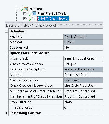
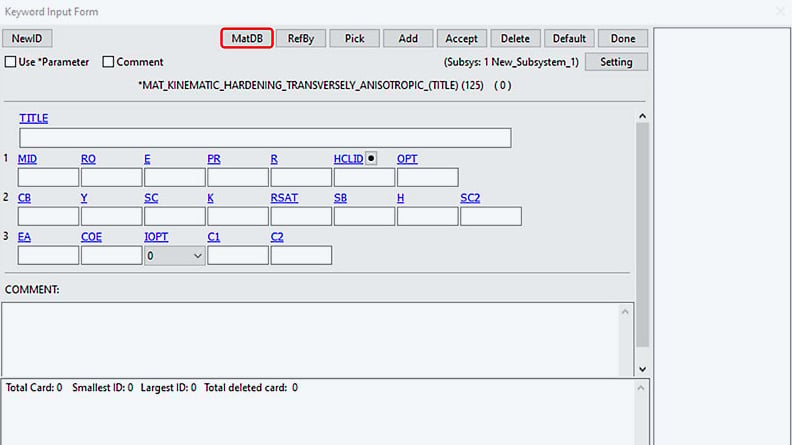
Definition of a SMART-Object for Analyzing Fatigue Crack Propagation with Ansys Mechanical | © CADFEM Germany GmbH 

Crack Propagation in Ansys is SMART

Given a defined initial crack, Ansys allows for the analysis of a stepwise crack progression under static or cyclic loading. The idea behind this is that the ratios of the calculated K-values at the crack tip can estimate the direction of further local crack development. Shear loads (K2 and K3 values) cause a straight crack to bend in the further course. Together with the magnitude of the K-values, a crack progression is then realized by remeshing at the crack tip.

The functionality is referred to in Ansys as SMART (“Separating, Morphing, Adaptive and Remeshing Technology”) and is defined with the corresponding object in the mechanical setup. Its definition refers to the initial crack already defined.

We continue to use the load cases under consideration as the load for our example. These should each be considered as pulsating. This is quantified by the R-ratio as in a stress evaluation. We therefore define R = 0. In the case of cyclic fatigue crack growth, a crack propagation is calculated in each substep, usually using the Paris-Erdogan equation. We therefore define a sufficient number of substeps. In our example, 100 for a maximum of 100 crack propagation increments to be analyzed. We deactivate automatic substepping as it is not needed for cyclic crack growth. The following figure shows an animation of the crack propagation.

Tech_Article_Bruchmechanik_cracking_cylinder_under_tension

Cyclic Crack Propagation in Cylinder with Pulsating Tension Load; Calculated using Ansys SMART | © CADFEM Germany GmbH 

Do pretzel sticks break correctly in Ansys?

The crack surfaces formed from the initial crack are presented in the figure below for the two load cases. For torsional loading, the axial crack quickly propagates into the expected 45° inclination. Under tensile loading, the crack spreads further normal to the axis. The crack front changes from an original circle to practically a straight shape. The fracture images correspond to those expected and ultimately correlate with the observed progressions of the pretzel sticks. So, Ansys calculates correctly or, to put it better, our pretzel sticks break correctly!

To support a possible damage analysis, we can now ask ourselves which load combination must prevail to achieve a 35° inclination of the crack surface to the axis normal. To do this, we combine normal and torsional loading in various proportions as cyclic load and calculate the crack progression with SMART. We have already done this and were able to iteratively determine a ratio of 55 % of the normal load and 45 % of the torsional load to reproduce the damage pattern.

Determining the duration at which a crack is spreading can be useful for both preventively and retrospectively in the event of damage. With knowledge of the required material properties, this information falls as a byproduct during the crack progression analysis. The figure shows a comparison of the crack propagation under tensile, torsional loading, and in our damage examination. The crack grows fastest under tensile pulsating load. In our damage case, the crack growth is slightly slowed down compared to pure tensile loading. This information can be useful, for example, in dating the crack origin in damage analyses or in deciding on a revision interval in preventive cases.

Tech_Article_Bruchmechanik_Crack-Growth-Cycle-Counts

Crack Growth over Cycle Counts | © CADFEM Germany GmbH

Tech_Article_Bruchmechanik_Calculated-Crack-States

Calculated Crack States for pure Tension, pure Torsion as well as Mixed Cyclic Loading | © CADFEM Germany GmbH 

Outlook

Perhaps we could open a small door to the possibilities that fracture mechanics has to offer with this contribution. Be assured, there is still a lot more that cannot be addressed within the scope of this article. This includes questions such as how large a crack is actually allowed to grow, as well as the question of the remaining cycle numbers – mentioned in the previous section – which was not shown in detail here.

Likewise, the possibilities of crack growth considerations in Ansys are far from exhausted with what has been said. For instance, the following questions remain unanswered: What other options for crack modeling are available? How can one account for the fact that cracks sometimes close during loading? According to which hypotheses is the direction of crack propagation determined? Can non-proportional load cycles be analyzed with Ansys? And what options are available to optimize computation times?

The CADFEM training “Life with Cracks” offers an in-depth exploration of fracture mechanics in Ansys Mechanical. We guide you step by step through the fracture mechanics capabilities of Ansys Mechanical and show you how to conduct a strength assessment according to the “fracture mechanicsFKM guideline using numerical calculations.

Cyclic Crack Propagation under Non-Proportional Loading and Nonlinear Contact Condition of the Cracked Faces | © CADFEM Germany GmbH

Training on the topic

Portrait_empty_Blog

Author

Klaus Graf

Engineering Services

+49 (0)8092 7005-733
kgraf@cadfem.de

Portrait_Blog_HDonner

Editor

Dr.-Ing. Hendrik Donner

CAE Engineer

+49 (0)8092 7005-725
hdonner@cadfem.de

Technical Editorial

Dr.-Ing. Marold Moosrainer

Head of Professional Development

+49 (0)8092 7005-45
mmoosrainer@cadfem.de