Mesh morphing with method: The heat exchanger
Malte Küper
17.07.2024
Tech Article | 24/06
You want to use the capabilities of the Ansys Fluent Adjoint Solvers for the free-form optimization of your design? Then you need to consider the mesh deformation method to be used. How complex is each method and how well are spatial constraints maintained? This article provides an overview using the example of a heat exchanger.

The optimization problem using a specific example
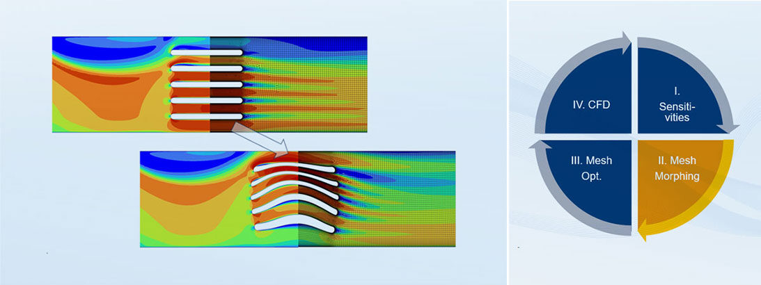
You have a design and are now considering geometric optimization? Ansys offers two essential approaches in the field of flow simulation: Parameter optimization and free-form optimization. In the realm of free-form optimization, you work without parameters and obtain displacement sensitivities of all wall nodes of your CFD mesh with respect to a target variable that you have defined, such as the reduction of pressure loss (Article 23/05). Over several design iterations, the optimization tool Gradient-Based-Optimizer gradually approaches the optimum. How the sensitivities result in a deformed mesh is the subject of this article.
Let's take a look at this using the example of a 2D heat exchanger located downstream of a 90° channel bend. In this setup, the pressure drop from inlet to outlet is chosen such that a flow velocity of 0.5 m/s is achieved at the inlet. The water has an inlet temperature of 20°C and the heat exchanger maintains a constant wall temperature of 90°C. The objective of the optimization is to maximize the heat flux from the heat exchanger to the water. By selecting these boundary conditions and the optimization objective, an increase in pressure loss is indirectly prevented, as this would lead to a reduction in mass flow, which would negatively impact the optimization objective.
A design iteration of the Gradient-Based Optimizer consists of calculating sensitivities, mesh deformation, and subsequent flow solution. We assume that we are in the middle of a design iteration, having calculated the sensitivities; the next step is mesh morphing. For mesh morphing, the Design Tool provides three methods: Direct Interpolation, Polynomials, and Radial Basis Function. In the next section, we will learn how these methods work, the mesh quality we can expect, and how well they handle Design Conditions.

Heat Exchanger and the Design Tool | © CADFEM
Which morphing methods does Fluent know?
Among Direct Interpolation, Polynomials, and Radial Basis Function, the simplest and least complex method is Direct Interpolation. In this approach, the deformation of the volume mesh is based on the weighted average of displacements of the boundary nodes. The displacement of the boundary nodes, in turn, is achieved by directly using the sensitivities along with a smoothing parameter. The disadvantage of this method compared to the other two is the high risk of obtaining a poor mesh quality. Additionally, in the case of non-conformal interfaces, there is a possibility of both sides of the interface moving away from each other.
In the Polynomials method, we first define a number of control points (CP) in each spatial direction of the area to be deformed. These control points are then shifted based on the sensitivities, although the actual mesh deformation is done by mapping the CP displacement onto the mesh nodes using Bernstein polynomials and B-splines. Due to the large-scale smoothing property of Bernstein polynomials, the Polynomials method has the advantage of maintaining mesh quality even with significant deformations. Since version Ansys 2023R2, the disadvantage of requiring small tolerances when using Design Conditions can be addressed with the Enhanced option.
The third method is the Radial Basis Function. In this approach, mesh deformation is interpolated based on the displacement of control points using a kernel function. In Ansys Fluent, the control points are the mesh nodes themselves, with the kernel function describing the influence radius of each node on its neighboring nodes. The Radial Basis Function method offers a good balance between maintaining mesh quality and efficiently handling Design Conditions. Similar to the Polynomials method, there is an additional option called Enhanced, which allows for the choice of larger tolerances when using Design Conditions.

Overview Morphing Methods | © CADFEM
Heat exchanger "in shape"
The optimization goal of maximizing the heat transfer in our heat exchanger inherently carries the issue that maximization problems are less robust than minimization problems. Therefore, we reformulate our goal under Observables as the minimization of the inverse of heat transfer. Additionally, we normalize the objective with the initial value so that we can always read the percentage change relative to the initial value during optimization. A reduction of the objective by 1.25% is aimed for each design iteration. The optimization will automatically stop when the Gradient-Based Optimizer reaches the convergence criterion.
In the Design Tool, we are now configuring all settings for mesh morphing. In the case of the heat exchanger, both the walls to be modified (wall_fins) and the walls not to be modified (wall_outer) lie within the region where mesh deformation is to be performed (see figure). Thus, despite the absence of Design Conditions, we have the requirement that the wall_outer zone must not be deformed during optimization. In the case of the Polynomials or Radial Basis Function methods, the Enhanced option is therefore necessary to avoid high computational costs with tighter tolerances.
For the three morphing methods under the settings described above, the results are as follows, showing significant differences both geometrically and in terms of goal achievement. The Direct Interpolation method achieved only a 5% improvement after 13 design iterations. Both the Polynomials and Radial Basis Function methods resulted in smoother mesh deformation and a greater reduction in the objective by 12% and 14% and within 16 and 22 design iterations, respectively. The differing results stem from the search for a local minimum, which is typical in gradient-based optimization methods.

Morphing Methods in the Example of Heat Exchanger Optimization | © CADFEM
Fluent Adjoint Solver – now it's your turn!
As the heat exchanger example illustrates, the optimization results can vary significantly depending on the chosen mesh morphing method – especially when differing local minima are encountered. Experience shows that the results from Polynomials and Radial Basis Function methods typically converge more closely and produce smoother deformations compared to the Direct Interpolation method. However, the latter is highly robust and requires minimal computational effort. Why not try out the methods on your specific example? Note: The Preview function of the Design Tool can provide an initial impression of the results.
Mesh Morphing is just one component within the application of the Adjoint Solvers for free-form optimization. Equally significant are the definition of the objective, the setup of the Gradient-Based Optimizer, and the correct choice of numerical settings and stabilization techniques. Did you know that you can perform multi-objective optimization at multiple operating conditions? And have you gained a deeper understanding of your design using sensitivities? The Ansys Fluent Adjoint Solver offers a variety of features that go far beyond simple geometry deformation or optimization of individual objectives. Take a look at our training course on this topic!

Preview Option of the Design Tool | © CADFEM
Training on the topic
-
Optimization of Flow Geometry Using Fluent Adjoint Solver

In this course, you will learn how to effectively apply tools available in Ansys CFD for shape optimization of your flow geometry.


Editor
Dr.-Ing. Marold Moosrainer
Head of Professional Development
+49 (0)8092 7005-45
mmoosrainer@cadfem.de
Cover images: Left: © CADFEM GmbH | Right: © CADFEM GmbH
First published: April 2024


