Python Scripting in Ansys Discovery - Only for Nerds?
Susanne Haase
15.07.2024
Tech Article | 23/07
Do you know this? You edit your geometry in Ansys Discovery and repeat the same sequence of operations over and over again. Quite annoying, isn't it? Wouldn't it be nice if automation could take care of such tasks? I'll show you how to get started with scripting in Ansys Discovery in form of a click tutorial, and in the end, you can decide for yourself how high the nerd factor is for you.

From the Idea to the First Python Script
When we think of programming, images of tons of code lines on the screen come to mind. Especially if you haven’t had much contact with Python, or any other programming language for that matter, the hurdles to even getting started with the first line of code can be great. In this article, I would like to guide you through the process of creating a Python script for geometry creation and would be happy if you tried out what is explained directly in Ansys Discovery while reading this.
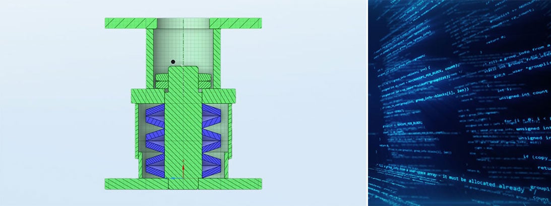
Let's imagine we have to fill a hydraulic cylinder with disc springs. The installation space is given, and the best configuration of number, arrangement and thickness of the springs is to be determined simulatively. Since a large number of different designs are to be calculated, it would be far too time-consuming to recreate each spring package manually. The first step in automated geometry creation is always to think about how we would proceed manually in the software. We would draw a disc spring, then draw a second one with a new center point, possibly turn it upside down, and with multiple repetitions, assemble the spring pack this way. We will now implement these steps programmatically.
What Python knowledge do I need for scripting in Discovery? For starters, the absolute basics are enough:
- for-loops
- if-statements
- lists.
If you also know what a function is, you can structure your code in a more efficient way. Being that this is IronPython 2.7 is only worth mentioning as a side note at first, since the various Python variants hardly differ in the basics.
The Script Editor in Discovery
For scripting in Discovery, we need the script editor, which is installed by default. Go to the Discovery main menu and open the script editor. The script editor is divided into two sections: the upper area, where the script is written, and the lower area, where the console is located. The console gives us feedback on our script. This could be output values, but also error messages.
For a first finger exercise, we enter a print command in the script area:
print("Hello World!")
When we run the script via the green triangle in the upper right corner, our text appears as output in the console.

The script editor can be found in the main menu of Ansys Discovery | © CADFEM Germany GmbH
The Record Button of the Script Editor - Your Friend and Helper
Now let's have the script construct our first disc spring. Let's briefly summarize how we would proceed manually. We would
- Switch to sketch mode
- Draw a parallelogram
- Switch to the solid mode
- Rotate the created surface by 360° using the pull tool.
When you open the script editor, the record button is already activated. Now we start drawing the disc spring and observe what the script editor records. The change from solid mode to sketch mode is easy to read:
sectionPlane = Plane.PlaneXY
result = ViewHelper.SetSketchPlane(sectionPlane, None)
We take the XY plane and set our sketch plane on it. When we start drawing the parallelogram, the script looks quite wild at first glance, since all automatically generated constraints are also recorded. But we can switch off the constraints and we get a well readable script. Two points are created and connected to a line. The entire procedure is repeated four times.
start = Point2D.Create(MM(10), MM(10))
end = Point2D.Create(MM(10), MM(6))
result = SketchLine.Create(start, end)

Disable automatically generated constraints | © CADFEM Germany GmbH
The script editor works in SI units. To avoid conversions, we can specify the correct unit directly in the script. In the next step, we switch back to solid mode.
mode = InteractionMode.Solid
result = ViewHelper.SetViewMode(mode, None)
After that, the disc spring gets its final design using the pull operation. The first three lines of the code snippet will be discussed in more detail in the next section.
selection = Face1
axisSelection = Axis1
axis = RevolveFaces.GetAxisFromSelection(selection, axisSelection)
options = RevolveFaceOptions()
options.ExtrudeType = ExtrudeType.Cut
result = RevolveFaces.Execute(selection, axis, DEG(360), options)
The only thing missing is to put a command at the very beginning of the script to clean up the graphics. Then the script always starts with an empty pane.
ClearAll()
The good thing is that we don't have to memorize or look up most of these commands, instead the script editor provides us with almost all commands via the record function and we can develop our scripts based on that. But it is always advisable to take a closer look at what has been recorded and clean it up.
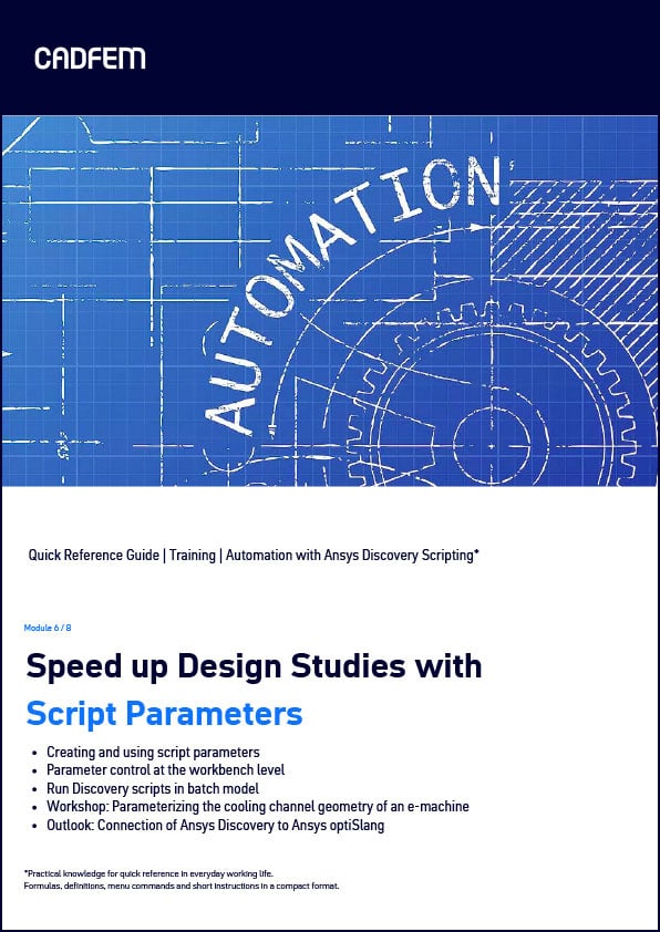
Quick Reference Guide (QRG): Speed up design studies with script parameters
The QRG provides you with an excerpt from our training course “Automation with Ansys Discovery Scripting”. Practical knowledge for quick reference in your day-to-day work, formulas, definitions, menu commands and short instructions in a compact format. Are you interested in the entire training course on this topic? You can find all the information here!
Download QRG for free
Refactorization of the Script - with the Broom through the Code
In software development, refactorization is the process of cleaning up and sorting source code to increase the readability and maintainability of code. I would like to show you the procedure using our example. In sketch mode, points are created to draw lines. Here it makes sense to bundle the Point2D definitions and make them more flexible using variables for the dimensions. This already makes the script for the sketching part look clearer:
D = MM(10)
D1 = MM(20)
H = MM(1)
H1 = MM(2)
ClearAll()
sectionPlane = Plane.PlaneXY
result = ViewHelper.SetSketchPlane(sectionPlane, None)
point1 = Point2D.Create(D/2, H1)
point2 = Point2D.Create(D1/2, H1-H)
point3 = Point2D.Create(D1/2, 0)
point4 = Point2D.Create(D/2, H)
result = SketchLine.Create(point1, point2)
result = SketchLine.Create(point2, point3)
result = SketchLine.Create(point3, point4)
result = SketchLine.Create(point4, point1)

Schematic representation of a disc spring | © CADFEM Germany GmbH
The second part of the script is about the pull operation. For this, we need the face that is created from the four lines when we switch to solid mode. On the one hand, we can access the face via the smart variables (these are the magenta variables in the script). On the other, we could define the selection by position in the structure tree, going through the list of bodies and from that, the list of faces. Since Python always starts counting at zero, the first body in the structure tree is at list position 0. GetRootPart() is always the top level in the structure tree:
In contrast to the smart variables, the index-based selection gives a transparent view in the script of where you are in the structure tree, but it is unstable with respect to changes in the structure tree if bodies are added or deleted. The index could possibly change. There is a third variant to access objects, which, in my opinion, is the most stable variant. In recorded scripts, there is very often "result = " in front of the commands. These result variables are not dead variables, but rather often contain useful information that we can use further. In our case, we can directly take the resulting face from the change to solid mode.
mode = InteractionMode.Solid
result= ViewHelper.SetViewMode(mode, None)
body =result.CreatedBodies[0]
The pull operation still needs the rotation axis. In the recorded script, the axis is selected first, and then the geometric axis is derived from this selection. We can do this more directly. If we move the mouse over the Execute of the RevolveFaces.Execute command, we see that a "Line" is expected as axis. Very often you can type "Line.Create(" into the script editor on the off chance and then you will be guided by the autocomplete hint texts.

Autocomplete in the Discovery script editor | © CADFEM Germany GmbH
selection = FaceSelection.Create(body.Faces[0])
axis = Line.Create(Point.Origin, Direction.DirY)
options = RevolveFaceOptions()
options.ExtrudeType = ExtrudeType.Cut
result = RevolveFaces.Execute(selection, axis, DEG(360), options)
Flying high with for-loops
We had planned to stack several disc springs on top of each other with the script. Anyone can construct a single spring, so we don't need a script for that. The disc springs should lie on the same axis, only the height should vary. If we stack n springs on top of each other, then the i-th spring has the height x +i*H1.
The best way to do this is to write the spring creation in a function. Functions in Python are characterized by the fact that they start with def, followed by a function name and possibly variables in a bracket. There is a colon at the end of the line. Unlike C++ or other programming languages, Python does not use curly braces or the like to indicate the beginning and end of a function. Instead, everything that belongs to the function is indented with a tab stop (equivalent to four spaces).
Now we can knit a for loop around our function. Our for loop starts with „for i in range(n):“. range(n) is a standard Python function to create lists. These lists go from 0 to n-1, so it has n elements. Same principle as for the function: everything that belongs to the for loop is indented by one tab stop. Depending on how big we choose n, our disc spring will be higher or lower. Feel free to try the following script directly in Discovery:
ClearAll()
def create_disc_spring(i):
D = MM(10)
D1 = MM(20)
H = MM(1)
H1 = MM(2)
sectionPlane = Plane.PlaneXY
result = ViewHelper.SetSketchPlane(sectionPlane, None)
point1 = Point2D.Create(D/2, H1+i*H1)
point2 = Point2D.Create(D1/2, H1-H+i*H1)
point3 = Point2D.Create(D1/2, 0+i*H1)
point4 = Point2D.Create(D/2, H+i*H1)
result = SketchLine.Create(point1, point2)
result = SketchLine.Create(point2, point3)
result = SketchLine.Create(point3, point4)
result = SketchLine.Create(point4, point1)
mode = InteractionMode.Solid
result = ViewHelper.SetViewMode(mode, None)
body = result.CreatedBodies[0]
selection = FaceSelection.Create(body.Faces[0])
axis = Line.Create(Point.Origin, Direction.DirY)
options = RevolveFaceOptions()
options.ExtrudeType = ExtrudeType.Cut
result = RevolveFaces.Execute(selection, axis, DEG(360), options)
n = 10
for i in range(n):
create_disc_spring(i)

Modulo calculation with Python | © CADFEM Germany GmbH
Optimize the spring stack with if-statements
To stack alternating oppositely directed springs, we need to draw every second spring in reverse. So we have to see if i is even or odd in the current function run. Mathematically, this can be done relatively easily with modulo, and Python also has the special character % for this purpose. If our number is even, the result is 4%2 = 0, if it is odd, then 5%2 = 1.
The if statement behaves like the for loop. All code that follows indented belongs to the if/else statement.
ClearAll()
def create_disc_spring(i):
D = MM(10)'
D1 = MM(20)
H = MM(1)
H1 = MM(2)
sectionPlane = Plane.PlaneXY
result = ViewHelper.SetSketchPlane(sectionPlane, None)
if i%2 == 0: # i is even
point1 = Point2D.Create(D/2, H1+i*H1)
point2 = Point2D.Create(D1/2, H1-H+i*H1)
point3 = Point2D.Create(D1/2, 0+i*H1)
point4 = Point2D.Create(D/2, H+i*H1)
else: # i is odd
point1 = Point2D.Create(D/2, H1-H+i*H1)
point2 = Point2D.Create(D1/2, H1+i*H1)
point3 = Point2D.Create(D1/2, H+i*H1)
point4 = Point2D.Create(D/2, 0+i*H1)
result = SketchLine.Create(point1, point2)
result = SketchLine.Create(point2, point3)
result = SketchLine.Create(point3, point4)
result = SketchLine.Create(point4, point1)
mode = InteractionMode.Solid
result = ViewHelper.SetViewMode(mode, None)
body = result.CreatedBodies[0]
selection = FaceSelection.Create(body.Faces[0])
axis = Line.Create(Point.Origin, Direction.DirY)
options = RevolveFaceOptions()
options.ExtrudeType = ExtrudeType.Cut
result = RevolveFaces.Execute(selection, axis, DEG(360), options)
n = 10
for i in range(n):
create_disc_spring(i)
Outlook on parameters and user buttons in Ansys Discovery
How do we proceed with the script now? The spring stack still must be installed in the cylinder. We can also measure the height of the cylinder chamber using a script command. If, for example, eight disc springs are to be installed, then we still have to do a bit of mathematics to calculate the appropriate height H1. It gets even more interesting when we start to parameterize the entire process. There is the possibility to define script parameters, which we can also control via the parameter manager on the Workbench project page. Through parameterization, a link to optiSLang also becomes possible.
Another possibility is to save the script as a user button in the Discovery Toolbar. Then you always have it at hand when you need it. You can also write prompts for user buttons via the so-called InputHelper. Then the user can specify e.g., the number of disc springs via the GUI after the button click. The user buttons can also be passed on to colleagues. This has the advantage that not everyone who wants to use such helpers must know about scripting in Discovery.
So, how nerdy did you find it? If you say it actually was okay, then feel free to run the script editor while using Discovery. Observe what commands are recorded and see if you can make the script work for you. Also feel free to look at the trainings that are linked below, which give you the opportunity to learn Python with other participants. If you value the benefits of automation but still find it too nerdy to take programming into your own hands, get in touch. We will find a solution with you together.
Training on the topic
-
Python Primer for Ansys

In this training, you will learn the basics of Python programming for using PyAnsys and automating your Ansys simulations.
-
Automation with Ansys Discovery Scripting

In this training course, you will learn to control Ansys Discovery via the script language Python: from geometry to simulation.
-
Intensive Workshop: Structural Mechanics

A must-have for all structural mechanics: After this workshop, you will look at your models with different eyes - guaranteed.


Editor
Dr.-Ing. Marold Moosrainer
Head of Professional Development
+49 (0)8092 7005-45
mmoosrainer@cadfem.de
Cover images: Left: © CADFEM Germany GmbH | Right: © Adobe Stock
First Published: October, 2023


