Understanding Electrical Discharges Using Field Simulations
René Fuger
10.04.2026
TechArticle 26/4 | Arc and discharge analysis for safety assessment
Why does an electrical discharge often ignite exactly where you wouldn’t expect it? Sharp edges, field maxima, and the smallest - often only tolerance related - geometric deviations determine when the dielectric strength of air is exceeded and an arc is formed. With field simulations, discharge mechanisms can be analyzed and designs can be specifically safeguarded.

Electric arc in the electrical industry with associated field simulation | © CADFEM / Adobe Stock
Summary
- Understand where discharges occur: Field simulations reveal hotspots, critical field strengths, and common misconceptions about arc and discharge paths.
- Simulate ignition and arc behavior: Coupled simulations allow numerical evaluation of the quantities that make physical discharges predictable in reality.
- Develop safe designs: Simulations make it possible to create robust designs against discharges, whether dealing with electrostatic discharges (ESD) or high voltage systems.
Fundamentals of Electrical Discharges
An electrical discharge occurs when the local electric field strength along a potential discharge path exceeds the dielectric strength of the medium. This threshold depends on the properties of the insulating medium - for air, this reference value is often around 3 kV/mm. The electric field strength, in turn, results from the charge distribution, which is significantly determined by material properties and geometry. Sharp edges, tips, or small radii lead to local field maxima - and these effects often shift the discharge away from the expected narrowest point toward the actual highest field concentration.
The Jacob’s ladder (horn gap) - two current carrying rods that open upward, forming an air gap - is a well known example from physics class or high voltage equipment. Horn gaps (also called horn gap arresters or horn fuses) were historically used to safely divert overvoltages to ground. When an excessive voltage occurs, an arc ignites between the horns, conducting current to ground. After ignition, the arc heats the air and rises due to the chimney effect. As the distance between the horns increases upward, the arc encounters an increasingly wide gap until it finally stretches and extinguishes.
Horn gaps are illustrative examples of arc formation and the interplay between electric fields and fluid mechanics. The same mechanisms act in connectors, power electronics, and relays as well as in electrostatic discharges (ESD) - with varying intensity and dynamics.

The simulated electric fields and field lines of a Jacob’s ladder | © CADFEM / ID: ENH6Q5
Analysis of Electric Fields and Hotspots
Between components that are at different electrical potentials, an electric field is established that can be strongly concentrated by small distances, tips, or sharp edges. An electrostatic simulation makes it possible to compute the fields on real 3D geometry models and thus identify critical areas early in the development process. By analyzing the field lines — which always run parallel to the electric field vector — it is possible to determine paths along which discharge routes are most likely and whether local field strengths become critical.
The actual field distribution depends on geometric dimensions, charge distribution, and material properties. These effects are not intuitively visible and only become apparent through electrostatic simulation prior to hardware setup. The simulation of the Jacob’s ladder example considered here showed that the edges of the metal rods amplify the local field. As a result, the initial discharge does not arise at the geometrically narrowest point but at the edges — a typical, often overlooked effect.
Discharges are therefore not random events but direct consequences of the field distribution. Anyone who understands where and why the field becomes too strong can avoid breakdowns — or deliberately create them — and thereby lay the foundation for analyzing the actual discharge ignition.

Simulated profile of the electric field strength along a path at different potential differences | © CADFEM / ID: K9MCLU
Simulation of Discharge Ignition
With the Inception Voltage analysis, as integrated in Ansys Maxwell, the breakdown voltage along a path with the highest field strength in a gas can be semi analytically estimated. The method evaluates the local field strength along a path and links it with the material data of the medium. This yields a voltage value at which a breakdown becomes likely. While pure electric field analysis only shows where a breakdown is likely to occur, the Inception Voltage analysis answers the question of at which voltage a discharge realistically becomes possible. The Inception Voltage indicates when it ignites — but not how the discharge subsequently develops.
An arc does not arise instantaneously; it develops over time — even if this time is very short. With Ansys Charge Plus, the temporal evolution of an arc can be modeled via coupled electric fields and gas physics, showing when the first free charge carriers form and how they intensify along a preferred path into a conductive plasma channel. The simulation of the Jacob’s ladder demonstrates this behavior clearly: As the current increases, the electron density initially rises locally, spreads along the strongest field line, and eventually forms a continuous channel.
This makes local effects visible that are crucial for engineering:
-
How quickly does the arc ignite - and what happens during the initial ignition and the discharge process?
-
Where does the plasma channel actually attach - at the narrowest point or at the strongest field maximum?
-
What current and voltage behaviors occur during ignition - and how sharply does the voltage drop when transitioning into plasma?
-
How do gas, pressure, or humidity influence the process - for example through the local dielectric strength?
This results not only in an illustrative visualization but also in a reliable physical basis for constructive decisions. It becomes clear that the ignition is not a random event but a determinable physical process.

Temporal evolution of the voltage and the local conductivity for several time points between the current rails of a Jacob’s ladder | © CADFEM / ID: JER24C
Tip
This seminar focuses on the simulation of electrostatic discharge (ESD) phenomena using Ansys Charge Plus – from physical modeling to technical assessment. Topics include electric discharges across air gaps, their triggering criteria, and their impact on electronic components and systems. Based on an end-to-end simulation workflow – covering geometry setup, meshing, parameter definition, and post-processing – participants learn how to realistically model and evaluate typical ESD scenarios.
Behavior and Dynamics of Electric Arcs
A stable arc forms when sufficient power is available in the system to keep the plasma permanently conductive. This interaction of electric currents, temperature fields, gas movement, and Lorentz force can be simulated transiently in a Maxwell–Fluent coupling. Once an arc has ignited, losses occur in the arc channel, leading to increased temperature and therefore lower gas density.
At the same time, the electric currents influence the magnetic field, generating Lorentz forces. To keep the coupled physics realistic, electromagnetic and fluid mechanical calculations must communicate with each other at every time step. It is important that the time step size is very small at the beginning in order to capture the effects well, and then increased during the simulation to keep the overall computation time as low as possible. System Coupling allows the time step size to depend on functions of the currently computed time.
For example, the function
10e-9[s] if Time < 50e-9[s] else (75e-9[s] if Time < 500e-9[s] else 1e-6[s])
enables a time step of 10 ns for the first 50 ns, then a time step of 75 ns until 500 ns is reached, and for the remainder of the simulation 1 µs steps are used.

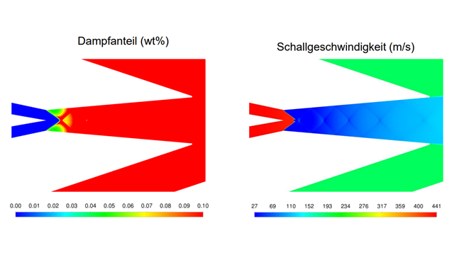
Multiphysically coupled simulation between electromagnetics (Ansys Maxwell) and fluid flow (Ansys Fluent) using a control tool (Ansys System Coupling) | © CADFEM / ID: 1P2BVH
The Jacob’s ladder demonstrates this interaction impressively: The arc does not rise due to a “mystical plasma property,” but because of the reduced gas density and the resulting thermal buoyancy. The position and shape of the arc change continuously — as do the flow and temperature fields. The same mechanisms also act in technical switching devices, in which an arc under load must be guided or displaced in a controlled manner.
A vivid example is the opening of a relay: When the contact opens, an arc forms, and this arc is pushed sideways out of the contact area by the magnetic field of the integrated permanent magnets. The magnetic field interacts with the current in the plasma channel and generates Lorentz forces that “blow out” the arc. A coupled Maxwell and Fluent simulation realistically represents this process: Maxwell provides current density, losses, and Lorentz force, while Fluent computes temperature fields, gas movement, and the modified conductivity. The arc behaves in the model exactly as known from experiments — a building block for reliable design decisions.

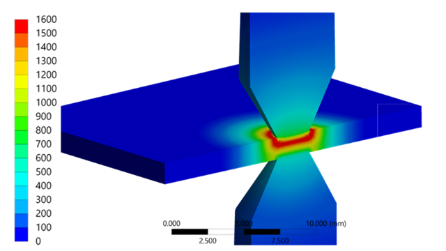
Blowing an arc out of the contact area of a relay using a magnetic field | © CADFEM / ID: Z1B6S2
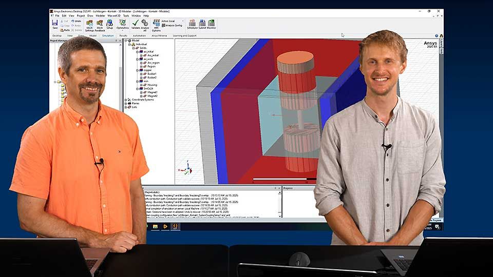
Let’s Simulate – Simulation of Electric Arcs
In this Let's Simulate series, Dr. René Fuger and Malte Küper demonstrate how electric arcs in high-performance switches for electrical machines are simulated in a practical manner. Using Ansys Maxwell, Fluent, and System Coupling, they create a coupled multiphysics model that combines electromagnetics, fluid flow, and temperature behavior. From geometry and material models to motion and evaluation, the two explain step by step how they proceed during their workflow. What is special here is that the expert from outside the field is guided through the simulation software, which opens up interesting prospects.
Benefits for Engineering and Development
The combination of field analysis, breakdown voltage, plasma formation, and coupled arc simulation makes it possible to identify discharge risks early and control them in a targeted manner. Instead of merely checking “works / doesn’t work,” it provides deep insight into where a discharge occurs, how it propagates, and under which conditions it remains stable. Based on this, assemblies can be made more robust, prototype iterations can be reduced, and the path to a safe, standards compliant design becomes significantly shorter.
For product designers and development engineers, this means: You not only recognize that a problem occurs, but can clearly understand why it occurs based on the simulated discharge paths, local field maxima, and arc behaviors. This physical transparency makes the decisive difference — whether through small adjustments to the geometry, optimized radii at potential hotspots, or targeted arc guidance using magnetic fields. Especially for components exposed to high voltage gradients during real operation, the deliberate control of the field distribution often determines whether an assembly reliably withstands 100, 10,000, or 100,000 switching cycles.
Those who want to dive deeper and not only observe discharge phenomena but actively simulate and master them will find the right tools and training at CADFEM: Participate in the seminar “Ansys Charge Plus for Electrostatic Discharges” and learn how to systematically analyze critical discharge paths, ignition conditions, and field hotspots. In addition, our Let’s Simulate on simulating electric arcs offers a direct look into the dynamics of real arc behavior and invites you to try the simulation yourself. These formats provide a practice oriented starting point for confidently developing your own high voltage, ESD, or arc applications.

High voltage ceramic insulators in a substation designed for discharge protection | @ Adobe Stock / ID: E87F63
More on the Topic
-
Webinar on Demand: Simulating Electric Arcing
Discover how to simulate electric arcs from ESD to arc faults. Gain insights into the physics, challenges, and risks across the full energy spectrum.
-
Training: Simulation of Electromagnetic Fields with Ansys Maxwell
From magnetostatics to magnetodynamics: Learn, how to easily model and simulate magnets, coils, etc. This training is offered as a 3-day course or alternatively as a self-paced eLearning course.
-
Training: CFD Simulations with Ansys Fluent
In this course, you will learn the relevant workflows for CFD simulation - from model selection, meshing and calculation to evaluation and quality control. This training is offered as a 3-day course or alternatively as a self-paced eLearning course.