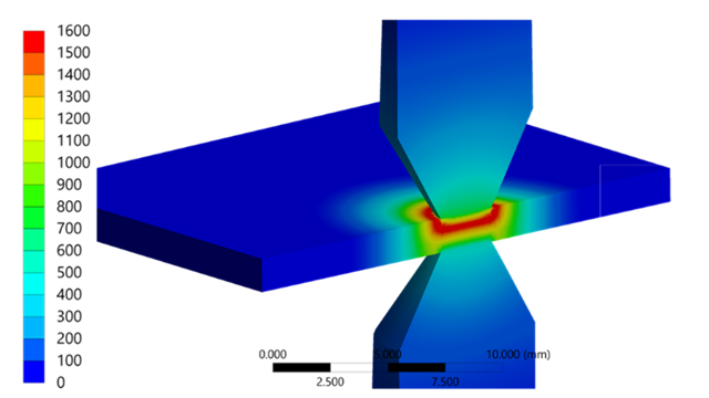
Anyone building a fluid or acoustic model meshes not the component itself – but the surrounding space. Creating this geometry is often the most time consuming part. The new Mesh Workflow in Ansys Mechanical eliminates this: meshing directly from the boundary mesh, without geometry creation. Once the principle is understood, users can build their own workflows - even for shells, layered models, or recurring tasks.

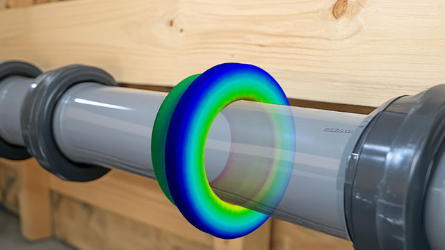
Speaker enclosure with an overlaid finite element mesh of the acoustic domain | © CADFEM / Adobe Stock

Inserting a Mesh Workflow via right-click on the Mesh object. | © CADFEM / ID: MR03NN
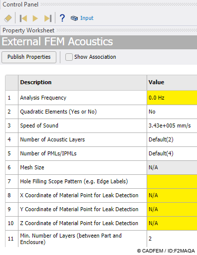
The Control Panel guides through the required inputs – shown here for the Acoustic Mesh Workflow. | © CADFEM / ID: F2MAQA

Outline tree with Input, Steps and Output – the loudspeaker box geometry (4 parts) serves as the starting point. | © CADFEM / ID: BNZWQR

The seven predefined Steps of the Acoustic Mesh Workflow – the result: loudspeaker box with fully meshed air volume "Air" listed under Geometry. | © CADFEM / ID: HKGZFI

"Complete Workflow" transfers the generated mesh back into Ansys Mechanical – as meshed geometry ready for further simulation. | © CADFEM / ID: 2C2CUL
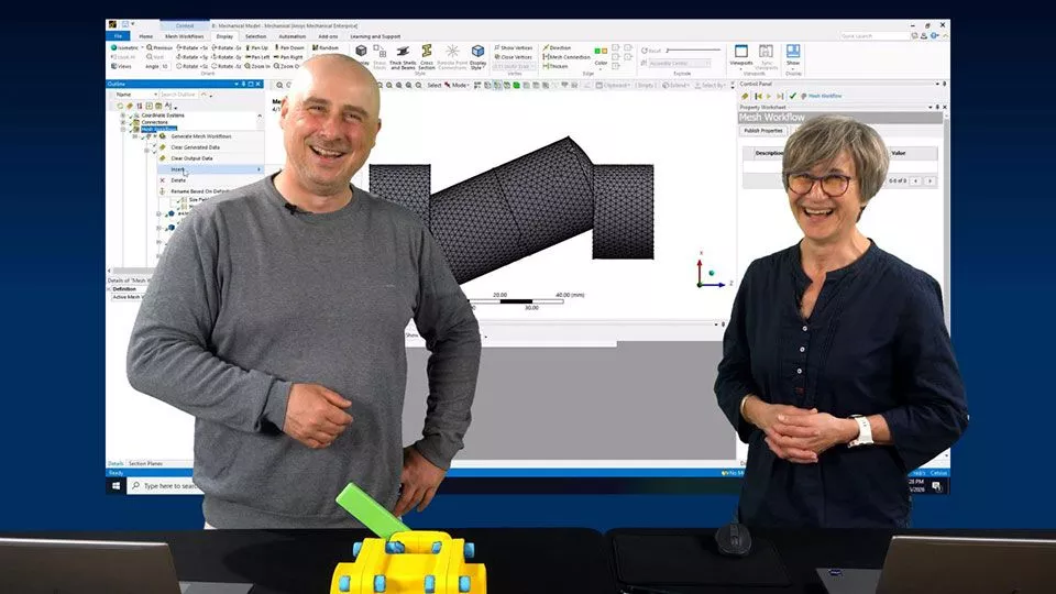
Transparent meshing processes using mesh workflows
Explore how Mesh Workflows in Ansys Mechanical bring transparency and reproducibility to the meshing process. This Let's Simulate covers custom Mesh Workflows, templates, and parameter control, alongside shell meshing and the meshing of acoustic and fluid domains. Learn how Mesh Workflows can replace Share Topology and discover how they compare to standard meshing in a range of specific applications.

With the Stacker Mesh Workflow – the complex layered structure with all through-holes as an extruded volume mesh. | © CADFEM / ID: AEU648

Custom Mesh Workflow for connecting and meshing independent surface bodies – connected at mesh level without shared geometry. | © CADFEM / ID: RUSKXA

Bolt meshed using the axisymmetric method – stored as a template in the Custom Mesh Workflow and ready for reuse. | © CADFEM / ID: A1BVPI

Export and import of a Mesh Workflow via the context menu. | © CADFEM / ID: L789FG