Contact Pressure Analysis in Ansys – A Tough Nut?
Andre Stühmeyer
17.07.2024
Tech Article | 24/05
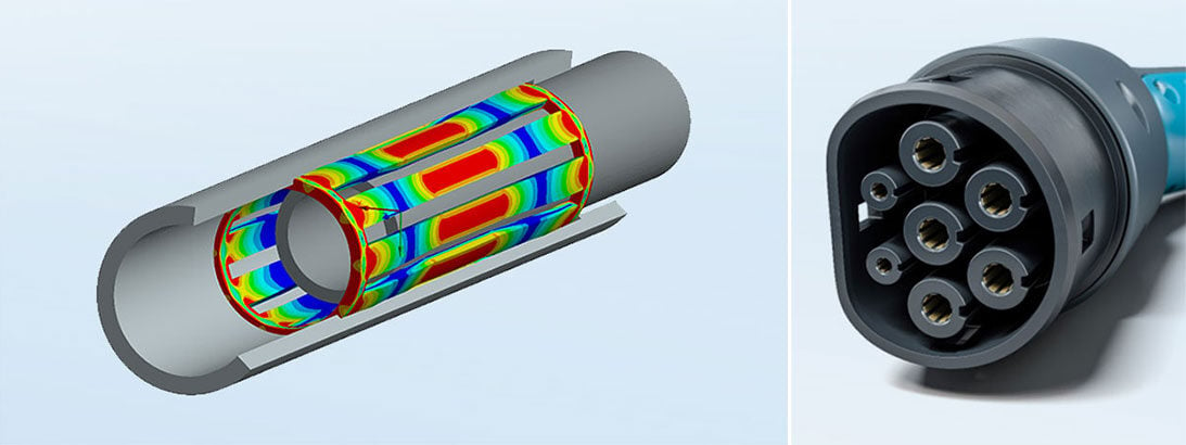
Contact calculations are ubiquitous in structural mechanics, and metrics like penetration and contact stiffness are constant companions. This article sheds light on situations where a stiffness of 8000 N/mm³ suffices and when you need to use a thousand times more, illustrated using an electrical connector.

Contact Calculation in Structural Mechanics
Contacts are encountered in most structural mechanics calculations. In simpler cases, these can involve bonded contacts, which are easier because they are linear contacts. However, there can also be frictional contacts, which are more challenging to compute. These contacts can open and close, and for closed contacts, it's necessary to differentiate between sticking and frictional sliding. Thus, frictional contacts lead to a nonlinear finite element (FE) analysis. During the calculation, the solver must iterate the status change in normal and tangential directions until force equilibrium is achieved.
Convergence depends on the contact formulation, contact search, and contact status. The latter indicates whether the contact is open or closed. If a contact is not closed at any point and a body is not further supported, rigid body displacements can occur. Therefore, it is crucial to ensure that contacts are closed, especially at the beginning of the calculation, but contacts can also open during the calculation. In the contact search, the solver must determine where the contact is closed. It is characteristic of nonlinear contact that the areas of closed contact are not known in advance; otherwise, boundary conditions could be used instead.
The contact formulation defines how the contact condition is integrated into the equation solution of the finite element problem. Here, a penalty method is commonly used. A key aspect of the method is that high stiffness between the contact nodes acts to prevent penetration. However, this contact stiffness influences convergence and results, and it's up to the user to adjust the stiffness, for example, in the case of small contact areas like Hertzian contact pressure. The contact stiffness will be discussed using a practical example of an electrical connector, where the primary focus is on determining contact force and area.

Hertzian contact pressure, the classic in contact calculation, with a depiction of the equivalent stress | © CADFEM Germany GmbH
What does the penalty method do?
In the penalty method, force pairs act that are proportional to the penetration between the penetrating bodies. This can be imagined as if stiff springs are tensioned between the contact partners. In nonlinear contact, these act only under pressure and are meant to prevent further penetration in closed contact. For this, the stiffness of the contact springs must be significantly higher than the structural stiffness, as the structure should deform and not the penetration in the contact increase. Therefore, it is logical that the solver initially derives a stiffness from the material in contact; in Mechanical APDL, the modulus of elasticity is incorporated.
This stiffness is weighted with element dimensions, leading to relatively high stiffnesses, which are suitable for bonded contact. However, in nonlinear calculations, this often results in unnecessarily high contact stiffnesses, leading to small step sizes in the nonlinear calculation. To improve convergence and efficiency, the stiffness is updated during the calculation based on the penetrations and the stresses in the underlying structure. The stiffness is measured as force per area and penetration, resulting in practice in contact stiffnesses that range from less than 0,1 N/mm³ to over 1,000,000 N/mm³.
It is also dependent not only on the material but also on the compliance of the structure. One does not automatically obtain the stiffness necessary for the calculation goal, and the user is faced with the question of whether the stiffness estimated by the solver in the calculation is sufficient for their task. If the penetrations are too high, other result sizes can be influenced and are inaccurate. It is up to the user to check whether the contact stiffnesses are sufficient for their purpose. This aspect of contact stiffness will be discussed in the following using an electrical connector connection.

Simplified model concept of penalty contact: stiff springs are installed in normal and tangential directions between the penetrating elements | © CADFEM Germany GmbH
Connector and Modeling
The electrical connector consists of an external sleeve and a plug. These two parts are connected via a spring. The spring and the plug have an interference fit, so when they are plugged together, the spring is deformed. The expansion of the spring results in a frictional insertion force that needs to be calculated. Subsequently, during operation, current flows through the plug, the spring, and into the sleeve. This current leads to heating of the components. Additionally, there is heating from the contact resistance, which nonlinearly depends on the contact pressure. For a nominal contact pressure (normal force per area), the contact area should also be determined.
The sleeve and plug are made of aluminum, while for the spring made of a copper alloy, plasticity is also considered. The spring is slotted and consists of 10 webs, but due to symmetry, only half a web is calculated. The calculation does not simulate the complete plugging process; instead, the spring and plug are positioned with an interference of 0.2 mm. In the first load step, the interference is pressed out (through a stepwise offset of the contact surface), and the normal force is established. In the second step, the sleeve is moved longitudinally, and assuming Coulomb friction with a friction coefficient of 0.15, the insertion force is established.
The contact force and contact area will now be investigated at varying contact stiffnesses. Without further user settings, the Ansys Mechanical APDL solver estimates the contact stiffness from material properties and element dimensions. Since contact stiffnesses vary over a wide range, an initial estimate is rarely appropriate, and an update occurs during the calculation based on structural stresses and penetrations. The lower limit of contact stiffness provides an aggressive update of 8100 N/mm3. In further variants, based on the program-controlled update, the stiffness is increased up to 18,500,000 N/mm3.

Top: electrical connector with sleeve (outside, only one half shown), spring, and plug (internal cylinder) in the installed position with interference Bottom: 18° segment for the calculation model | © CADFEM Germany GmbH
Impact of Contact Stiffness on the Results
The primary evaluations are the insertion force and the contact area. It is observed that the insertion force increases from 0.499 N to 0.502 N. The insertion force is directly proportional to the normal force, which changes accordingly. (Note: The forces apply to the modeled segment, which includes half a web. Therefore, for 10 webs, the total insertion force is 2x10x0.5 N = 10 N). In the examined range of contact stiffness, there is only a minor influence on the resulting forces.
This is also observed when evaluating the contact area in relation to the contact stiffness. Initially, a linear contact across the entire web width with an area of 0.15 mm² is established. With increasing stiffness, the contact area at the edge of the web becomes point-like and reduces to 0.00677 mm² at a stiffness of 18,500,000 N/mm³ (Note: The areas apply to the modeled segment, which includes half a web. Therefore, for 10 webs, the total area is 2x10x0.00677 mm² = 0.135 mm²). Thus, the contact area does not change in the percentage range but approximately by a factor of 20.
A similar behavior is observed for other metrics like penetration and nominal contact pressure. The penetration decreases by about a factor of 100 and, according to the simulation, is only 33 nm. If such small penetrations still cause a change in the results, a study regarding manufacturing tolerances should be conducted. The value of the nominal contact pressure has also increased by a factor of 25 and is about 500 MPa at a stiffness of 1.86e7 N/mm³. However, at the contact surface, it is observed that only a few elements are in contact, which means the influence of meshing must also be examined.
|
Contact Stiffness |
Insertion force |
Contact Area |
Max. Penetration |
Nominal contact pressure |
|
|
|
|
|
|
|
1,86E+05 |
0,501 |
0,0425 |
9,90E-04 |
78,59 |
|
1,86E+06 |
0,502 |
0,009725 |
1,40E-04 |
344,13 |
|
1,86E+07 |
0,502 |
0,0067615 |
3,30E-05 |
494,96 |
Table 1: Contact area and insertion force, as well as maximum penetration and nominal contact pressure, depending on the contact stiffness

Contact pressure at 8100 N/mm³ between spring and plug (top) and contact pressure at 1,850,000 N/mm³ (bottom) | © CADFEM Germany GmbH
How does mesh refinement affect the results?
The contact stiffness is a numerical parameter that should not have any significant influence on the results being calculated. Just as mesh refinement in finite elements should eventually no longer change the results, increasing the contact stiffness should also show a convergence of the result sizes. If one looks at the preceding results, this is not the case with the contact area. In the case of the contact area, however, it is not sufficient to only increase the stiffness. With an element edge length of 0.05 mm, only a few elements are in contact. Therefore, it is not enough to just increase the stiffness; the mesh must also be refined simultaneously.
Reducing the mesh edge length by a factor of 10 to 0.005 mm results in a contact area of 0.0072 mm², indicating that the previously coarse mesh underestimated the actual area. The insertion force remains at 0.502 N, and a nominal contact pressure of 465 N/mm² is established. The maximum penetration is 1.3e-5 mm. With these results, the calculation using a mesh edge length of 0.005 mm, as well as the final contact stiffness of 34,700,000 N/mm³, show converged values, meaning further mesh refinement or higher stiffness no longer alters the result.
With the coarser mesh, the convergence worsens when the initial penetration is pushed out. While the first calculation with 8100 N/mm³ requires only 86 iterations, at 18,600,000 N/mm³ it takes 176 iterations and twice the computing time. The fine mesh with 0.005 mm edge length and 34,700,000 N/mm³ contact stiffness requires 282 iterations. Coupled with more than an 11-fold increase in the number of nodes and more than a 3-fold increase in the number of iterations, the computational effort escalates from minutes to nearly a day to precisely calculate the contact area. This is typical for point-like contact of stiff bodies, where accurate contact area calculation is associated with significant computational effort.

Contact pressure at 0.005 mm element edge length and 34,700,000 N/mm³ contact stiffness | © CADFEM Germany GmbH
How is the influence of stiffness explained?
The contact area can thus be calculated for the connector with relatively high effort by adjusting the contact stiffness. However, the insertion force is more or less independent of the contact stiffness. Why is one result size so dependent on the stiffness while the other is not? The spring has an interference of 0.2 mm compared to the plug. This interference must be pressed out in the contact, causing the spring to deform by about 0.2 mm. The penetration is in the micrometer range and is thus two orders of magnitude smaller. If the penetration is reduced and the spring deflection in the micrometer range increases, then the spring deflection only changes in the percentage range, and thus also the spring force.
The situation is different with the contact area. Across the spring, there are small gaps in the range of a few hundredths of a millimeter and smaller. Around the closed contact area, there are large regions with gaps in the micrometer range compared to the closed contact area. Therefore, a low contact stiffness with penetration in the micrometer range leads to a significant change in the contact area. The penetration is in the same order of magnitude as the surrounding gap. The influence of contact stiffness is explainable, but in case of doubt, a study is necessary to confirm the results, as is common with element sizes and other numerical parameters.
The user must therefore assess the impact of penetration on the result metrics they are evaluating. Not all result metrics are sensitive to contact stiffness. However, the contact area, especially at line and point contacts between equally stiff bodies, requires very stiff contacts.

Contact gap between spring and plug | © CADFEM Germany GmbH
Multiphysical Design of the Connector
The location and size of the contact area, as well as the contact pressure, can be used for further design of the connector concerning its ampacity. As already mentioned above, the current flow through the plug, spring, and sleeve leads to heating due to the resistance in the materials. This results in heat conduction within the components and a transition to the environment (convection, adjacent components). The temperature distribution, in turn, changes mechanical properties such as the modulus of elasticity and yield strength. The deformation affects the geometry and contact areas, leading to interactions with the electrical field and the temperature field.
Additionally, there is heating at the contact points, which depends nonlinearly on the contact pressure. This is due to the increase in the actual area of contact, as roughness peaks are flattened, and more peaks come into contact, thereby increasing the conductivity of the contact area or decreasing its resistance. Especially in the case of the temperature field, the conductivity of the fluid between the contact partners also plays a role, due to thermal conductivity and the size of the remaining gaps. Based on the CAD data with perfect surfaces, the real contact area, resulting from roughness, is not depicted. Instead, a conductivity in the contact is defined depending on the contact pressure.
The interaction between the physical domains of mechanics, temperature, and electricity can be examined in a coupled field analysis. In this context, it's crucial that contact forces, pressures, and areas are calculated accurately, which underscores the significance of contact stiffness. Typically, Ansys Mechanical's algorithms provide contact stiffnesses that are appropriate for the situation, but as demonstrated, adjustments may need to be made for specific use cases. Starting from the mechanical model, the simulation can now be expanded to include the electrical and thermal fields, allowing for the calculation of the current-carrying capacity while considering the nonlinear conductivities.

Dependence of Thermal Conductivity on Contact Pressure | © CADFEM Germany GmbH
Training on the topic
-
Contact Modeling with Ansys Mechanical

Learn how to use appropriate linear and non-linear contacts & improve performance and accuracy of your assembly simulations.
-
Intensive Workshop: Structural Mechanics

A must-have for all structural mechanics: After this workshop, you will look at your models with different eyes - guaranteed.
-
Intensive Workshop: Structural Mechanics

In this training, you will learn about the theory and practical application of coupled field simulation for the interaction of mechanics, temperature and electricity.
Let’s Simulate on the topic
-
The wonderful world of convergence

Dr. Hendrik Donner and Andre Stühmeyer are discussing what keeps everyone from structural mechanics busy: convergence.


Editor
Dr.-Ing. Marold Moosrainer
Head of Professional Development
+49 (0)8092 7005-45
[email protected]
Cover images: Left: © CADFEM GmbH | Right: © Adobe Stock
First published: April 2024


