NVH Effects in Drivetrains: Too Complex for Simulation?
Claus Kirner
06.02.2026
TechArticle 26/2 | Why Transient MBD Simulation with Ansys Motion Makes All the Difference
The answer is no. Use the Ansys Motion Drivetrain Toolkit: Within the operating range of electric drivetrain systems consisting of e machine and gearbox, disturbing effects such as whining or rattling can occur. Causes and potential damage consequences can be simulated quickly and efficiently across the entire operating range – e.g., a run up to maximum speed – in a transient simulation.
Noise exciting vibrations in an electric drivetrain | © CADFEM / Adobe Stock / ID: 5OOJLB
Conclusion
-
Understand NVH Causes: Electric drives and gearboxes generate dynamic excitations such as whining, rattling, and resonances. Key factors include the interaction of motor frequencies, gear mesh, and housing mode shapes
-
Simulate Transiently: The Ansys Motion Drivetrain Toolkit efficiently represents shafts, bearings, and gears as flexible bodies. Time‑dependent simulations across the entire run‑up reveal critical frequencies, gear mesh effects, and structural resonances.
-
Evaluate Acoustics: Results from the MBD simulation can be used directly for acoustic analysis – in the Motion post‑processor or coupled with Ansys Mechanical and Ansys Sound. This enables early evaluation of sound pressure level, tonal components, and psychoacoustic criteria.
From Noise to Solution: Acoustics as a Design Factor?
In the development of modern drivetrain systems, the topic of NVH – Noise, Vibration, Harshness – is becoming increasingly important. This applies not only to electric machines, as you read in the previous TechArticle of this series, but also to gearboxes in combination with electric machines, where noise development is a key quality factor. Vibrations in the housing lead to disturbing noise and can also influence the structural integrity of components. The stakes are even higher for precision or optical drives: here, even the smallest excitations and resonances reduce manufacturing or imaging quality. Both aspects highlight the importance of identifying and controlling vibrations early.
Counteracting NVH problems is a challenge. In practice, pragmatic measures are often used to mitigate acute disturbance frequencies: for example, cladding the housing with sound‑absorbing materials or increasing mass to shift frequencies. These “blunt” passive approaches may help in the short term, but they are rarely efficient and usually come with disadvantages such as increased weight, additional space requirements, or higher material costs. A targeted process‑based optimization of structure and acoustics starts as early as possible in development and requires a deep understanding of the physical relationships.
Simulation enables this process‑based optimization. To succeed, the simulation must reflect reality: NVH effects arise dynamically – during start‑up, acceleration, or load changes. Only time‑dependent simulation reveals when critical frequencies occur and how they evolve during run‑up. This allows causes to be identified and countermeasures derived before the first real component is manufactured. The Ansys Motion Drivetrain Toolkit uses multibody simulation (MBS) as a method to represent drivetrain structural behavior and simulate dynamic systems in the time domain.

Sound‑absorbing materials on the engine block | © Adobe Stock / ID:1INWNX
Fast Solving for Complex Drivetrain Models?
A typical operating range of an electric drive unit spans from zero revolutions per minute up to five‑digit speeds. Let’s calculate how many time steps you need for the run‑up of such a system:
- The decisive factor for time resolution will be the excitation frequencies generated in the motor and the first gearbox stage.
- The determining factors for the number of time steps are the duration of the run‑up and the maximum speed reached.
Thirty milliseconds of torque profile already cover a full revolution at 2000 rpm. Let’s imagine a drive whose harmonics in the first stage require a resolution of 360 steps per revolution (i.e., 1.0‑degree steps), which is not unusual. For a run‑up from zero to 12,000 rpm within 3 seconds, you need around 108,000 result time steps. Unthinkable to compute this with contacts between fully meshed gear bodies. The same applies to rolling bearings. The solution is the Drivetrain Toolkit with special modeling techniques for gears and rolling bearings.
The key phrase is “Fast Solving”: the modeling must enable fast calculations and vibration analyses in the time domain. To achieve this, the toolkit uses simplified gear and bearing models that nevertheless capture all essential nonlinear effects. For gears, an FE‑based stiffness model is used that divides the gear into slices and calculates substitute stiffness at the contact points. All ball and roller bearings, gears, and shafts (straight or conical, solid or hollow) can be generated parametrically, via external data, or tabularly, and bending and torsion effects are also considered.
Code:
# import libraries
import os
from ansys.geometry.core import launch_modeler_with_discovery
# create string with discovery code
cmd = """
# fix Small Faces with a smaller width of 1.5 mm
FixSmallFaces.FindAndFix(FixSmallFacesOptions(Width=MM(1.5)))
# define variables
bending_face = None
z_bending_face = float('inf')
# loop through faces
for face in GetRootPart().Bodies[0].Faces:
# get z coordinates and shape
z_cordinates = face.EvalMid().Point.Z
shape = face.Shape.Geometry.ToString()
# get bending face on the bottom
if (shape.Contains("Cylinder")):
if(z_cordinates < z_bending_face):
z_bending_face = z_cordinates
bending_face = face
# […] identify other important faces (clamping faces for example)
# save the faces in named selections
Selection.Create(bending_face).CreateAGroup("bending_face")
# […] also save other faces in named selections
"""
# create a text file and input the discovery code
fd = os.getcwd()
path = os.path.join(fd, "discovery.py")
with open(path, "w", encoding="utf-8") as file:
file.write(cmd)
# start discovery, open the geometry and run the code
modeler = launch_modeler_with_discovery(product_version = 251, hidden = True)
design = modeler.open_file(os.path.join(fd,"geometry.step"))
modeler.run_discovery_script_file(os.path.join(fd,"discovery.py"))
# save the finished geometry and delete the code file
design.save(os.path.join(fd,"geometry_prepared.scdocx"))
modeler.close()
os.remove("discovery.py")
Code:
# import libraries
import os
import ansys.meshing.prime as prime
from ansys.meshing.prime.graphics.plotter import PrimePlotter
# start client and assign lucid meshing
prime_client = prime.launch_prime()
model = prime_client.model
mesh_util = prime.lucid.Mesh(model=model)
# define path to geometry
fd = os.getcwd()
input_file = os.path.join(fd," geometry_prepared.dsco ")
# create a surface mesh
mesh_util.read(file_name=input_file)
mesh_util.surface_mesh(min_size=2.0)
# create a volume mesh and display
mesh_util.volume_mesh()
display = PrimePlotter()
display.plot(model, update=True)
display.show()
# save mesh
mesh_file_cdb = os.path.join(fd, "mesh.cdb")
mesh_util.write(mesh_file_cdb)

Tabular creation of bearings, gears, and shafts in Ansys Motion | © CADFEM / ID: DOWRZV
Let’s Simulate – Electric Drive Design with Ansys Motion Drivetrain Toolkit
Do you work on the development of vehicle drive systems? In this season, Dr.-Ing. Claus Kirner and Oliver Siegemund focus on the interaction between gearbox, electric machine and complex mechanisms, showing how a complete multibody simulation model is created in Ansys Motion.
Whitepaper
Correlation of the FE Model with the Real World
For structural-dynamic simulation, it is crucial that the eigenmodes and eigenfrequencies of the FE model match reality as closely as possible. Many model parameters, such as contact stiffness of joints, are vague or largely unknown.
The parametric correlation of an FE model with an experimental modal analysis (EMA) using the NVH Toolkit in Ansys Mechanical and Ansys optiSLang is described in a White Paper.
Request WhitepaperWhat Else Do I Need for Model Setup?
With the Ansys Motion Drivetrain Toolkit, you have already conveniently defined all shafts, bearings, and gears. For creation, you used the tabular input inside the Mechanical environment of Workbench. Now you only need the CAD data for your housing components and the electric motor, if you want to use a Maxwell import for electromagnetic forces. From Maxwell 2D, you import the air‑gap forces for a complete speed sweep and map them to rotor and stator. Ansys Motion automatically interpolates the correct values for the matching speed and angular position.
Just like rotor and stator, you mesh the housing parts using the Ansys Mechanical meshing algorithm. All meshed parts are defined as flexible bodies. This follows the “Fast Solving” principle in Ansys Motion and uses Component Mode Synthesis (CMS), which significantly reduces the number of degrees of freedom. Attend the Seminar for Structural Dynamics und Vibration Technology to learn how to reduce degrees of freedom by several orders of magnitude and thus accelerate computation.
For both housing components and shafts, “attachments” are defined. Here, bearing inner rings and gears are fixed onto shafts, bearing outer rings onto housing components. With a single click, you generate all geometry that you previously defined in tabular form. The bodies then appear as components in the geometry section of the structure tree. This defines the complete force flow from the electric motor through the gears and bearings to the housing components. All components in the force flow are flexible and therefore well‑suited for NVH analyses. Finally, a run‑up scenario (acceleration curve at the output) is defined and the simulation is started.

Drivetrain Model Setup in Ansys Motion | © CADFEM / ID: 9FYCCO
Which Result Quantities Can Be Evaluated?
The transient result dataset makes it possible to evaluate accelerations, deformations, and stresses at each individual time step. In addition, eigenfrequencies and mode shapes of flexible components can be analyzed. During run‑up in this example, the first mode is excited – shown here as superimposed vibration maxima of the motor housing during run‑up. Due to the mounting position of the housing, the housing is excited into resonance, for example by residual unbalance (bending vibration) of the rotor shaft and the motor frequencies of the e‑machine.

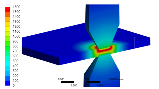
Excited first mode during run up, evaluated in the Ansys Motion post processor | © CADFEM / ID: BJILOZ
When evaluating the results of a virtual acceleration sensor on the motor housing, mode‑typical increased acceleration amplitudes appear. The Ansys Motion post‑processor makes it possible to create a waterfall diagram. Within this diagram, exciting frequencies and their harmonic orders can be distinguished. Based on this, the engineer can take measures such as modified bearing support or housing stiffening to avoid resonance.
In addition to motor frequencies, the gear mesh frequencies and their harmonics can be identified as excitation sources. In the context of an e-machine + gearbox combination these are the whining noises mentioned at the beginning of the article. Ansys Motion also allows adjusting the micro‑geometry (e.g., profile crowning and tip relief) of the gearing. This enables entering deviations from the involute profile to improve tooth load distribution. The effect becomes visible immediately in a tooth contact pressure distribution plot or in the waterfall diagram across the entire speed range. How to implement these steps in detail is taught in the Ansys Motion seminar.

Housing acceleration and waterfall diagram in the Ansys Motion post processor | © CADFEM / ID: USU2F5
After the Run-Up Comes the Acoustic Evaluation?
Once the run-up in Ansys Motion is completed with adequately dimensioned machine elements, the analysis is not yet finished: in addition to acceleration plots and waterfall diagrams, Ansys offers two approaches for acoustic evaluation. First method: Fast approximation in the Motion postprocessor: Here, the sound pressure level is calculated from the vibrations of the housing surfaces. A virtual microphone defines the position, the results appear as a chart and can be transferred directly to Ansys Sound – including listening simulation and psychoacoustic quality evaluation. You will learn how to perform these steps safely in the Ansys Sound seminar.
Second method: Coupling with a 3D acoustic field calculation in Ansys Mechanical: Surface velocities from Ansys Motion are transferred to the acoustic simulation in Ansys Mechanical. The surrounding air volume (negative model) serves as the FE model. The e‑machine + gearbox unit including housing is subtracted from the acoustic region and the imported data is applied as load to the negative model. This allows precise determination of frequencies and sound pressure levels. For large datasets, limiting the scope to selected time ranges is recommended, as a complete run‑up produces enormous data volumes.
The Ansys Motion Drivetrain Toolkit enables the design and evaluation of complete electric drivetrain systems – whether for industrial applications such as wind turbines or mobility. Advantages include the simple model setup within the familiar Mechanical environment and integrated methods for bearings, gears, and flexible bodies that allow fast time‑domain simulations. Have a look at our Let’s Simulate on the Ansys Motion Drivetrain Toolkit to leverage the tool for your projects. The multiphysics portfolio of Ansys enables direct transfer of results for harmonic acoustic analyses. In addition, stress and strain data can be used in nCode for lifetime evaluations. More on this in an upcoming article of this TechArticle series …

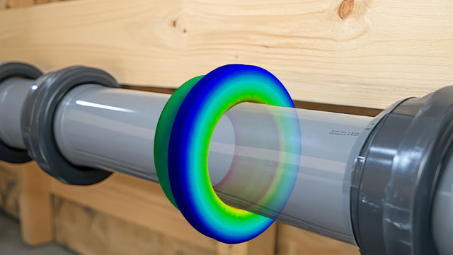
Acoustic analysis in the Ansys Motion post processor or with harmonic acoustics | © CADFEM / ID: N29IVL
More on the Topic
-
Let’s Simulate – Electric Drive Design with Ansys Motion Drivetrain Toolkit

Do you work on the development of vehicle drive systems? In this season, Dr.-Ing. Claus Kirner and Oliver Siegemund focus on the interaction between gearbox, electric machine and complex mechanisms, showing how a complete multibody simulation model is created in Ansys Motion.
-
Multibody Dynamics with Ansys Motion

Discover the possibilities of multibody simulation with Ansys Motion – from model setup and contact definitions to flexible body integration.
-
Bringing Simulation Models to Life with Ansys Sound

Discover the quality of the sound generated by your virtual products and learn how to assess this in terms of psychoacoustic criteria.