Shape optimization of a heat exchanger
Malte Küper
16.07.2024
Tech Article | 23/05
Engineers are constantly faced with optimization tasks: How can the component be designed to achieve an increase in efficiency? Where is the greatest influence? In fluid mechanics, things get even more complex; nonlinear effects lead to unclear cause-and-effect principles. Read here how the Fluent Adjoint Solver can be used to optimize a heat exchanger.

Parameter optimization or free-form optimization?
When it comes to the question of whether parameter or free-form optimization should be carried out, the sequence is more important than the decision to use one of the two methods. Parameter optimization first determines the general dimensions and process parameters (for example, the number of cooling fins) then free-form optimization unfolds the full potential of the design. In the example shown here, we assume a pre-optimized heat exchanger that should cool a heated plate (see Fig.: 1, Heat Exchanger (bottom)). The optimization task is to reduce the temperature of the plate as much as possible only by deforming the flow path.
Let's take a step back and generate the next logical questions from our objective: At which point in the heat exchanger do you need to start to increase efficiency? Where do geometry changes have the greatest effect? When we think of parameter optimization, to reduce the computational effort, we want to use geometry parameters only where significant influences on our target parameter are expected. Since the Fluent Adjoint Solver already provides information on sensitivities based on only one CFD calculation, it can be used not only in the sense of free-form optimization, but also in the sense of parameter selection or identification of influential areas.
As the above execution shows, the Fluent Adjoint Solver is not an optimizer in the strict sense, but rather a tool for the identification of sensitivities, in combination with the mesh morphing based on sensitivities the actual freeform optimizer results. Since the sole consideration of sensitivities with respect to a freely selectable target variable in the design process can already answer many questions, we first focus on the sensitivities themselves and less on the optimization that follows. The Adjoint Solver can be found together with the complementary tools in the Fluent GUI under the Design item (see Fig.: 1, Design Tab (top)).

Fig.: 1 Design Tab (top); Heat Exchanger (bottom) | © CADFEM (Austria) GmbH
Adjoint Solver: Where do the sensitivities come from?
Although the Adjoint Solver does not work with parameters in the actual sense (e.g., diameters, distances, etc.), it still has input variables such as cell coordinates and boundary conditions, the combination of which we want to understand here as an input vector (see Fig.: 2 Calculation of sensitivities). Classic sensitivity analyses would determine the respective effects on the target variable based on small changes of the input vector. Since a new CFD analysis must be performed for each of these changes, this approach is neither economical nor purposeful for typical CFD meshes (order of magnitude 1 million cells).
But how can the influences of the entire input vector be determined without a classic sensitivity analysis? The Adjoint Solver uses a mathematical trick here, in which the sensitivities are calculated by solving a new differential equation on the already existing mesh. All that is needed is a previously performed CFD analysis. It should be noted that, in contrast to fluid mechanics, these are linear relationships, whose prediction quality therefore decreases with large changes in the input vector.
Since we typically deal with free-form optimizations in the context of the Fluent Adjoint Solver, the sensitivities of the walls with respect to a target size are of particular interest. However, the results give a much deeper insight into the design. For example, the effects of additional turbulence or local heat sources or sinks can also be estimated.

Fig.: 2 Calculation of sensitivities | © CADFEM (Austria) GmbH
Increasing the efficiency of a heat exchanger
For our heat exchanger, we first need a CFD calculation. The boundary conditions are a total pressure of 100 Pa at the inlet, a static pressure of 0 Pa at the outlet and a heat flux of 10 W across the base plate. Thermal losses to the environment are neglected. The specification of a pressure gradient has the advantage over a mass flow boundary condition of preventing a potentially unfeasible constriction of the flow channel. The CFD analysis shows a clear non-uniform distribution of temperature and heat flux density between the four channels (see Fig.: 3 CFD results and sensitivities, No. 1 and No. 2).
The target variable in this case is obvious: the temperature averaged over the heated plate. For the Adjoint Solver, it initially does not matter whether it is a minimization or a maximization task, since this only results in sign reversed sensitivities. The direction of the sensitivities is only significant for post-processing and optimization. Initially, we work with first order discretization methods, since, to begin, the direction and location of the sensitivities are more important than their magnitude. Moreover, higher order methods provide the necessary additional accuracy only near an optimum. Optional stability methods help to improve the convergence behavior.
The plot of the sensitivity vectors shows that, in particular, the entrance region into the vertical channels has a large influence on the target variable (see Fig.:3 CFD results and sensitivities, No. 3). The vectors here indicate the direction in which the walls would have to be deformed to reduce the surface temperature of the heated slab. For a subsequent free-form optimization, this means that the largest changes are to be expected in this region. For parameter optimization, this gives us an indication of efficient geometry parameter placement. The sensitivity, with respect to the turbulence, shows that in the area of the channels, an increase of the turbulence near the wall would lead to a temperature reduction of the plate (see Fig.: 3 CFD results and sensitivities, No. 4).

Fig.: 3 CFD results and sensitivities | © CADFEM (Austria) GmbH
The free-form optimization
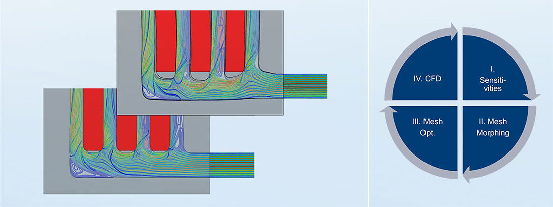
The sensitivity-based free-form optimization is found under the menu item Gradient-Based Optimizer. Since the predictions of the sensitivities are linear, the path from the start design to the target design is divided into several design iterations. Here, a design iteration consists of 4 steps:
- Calculation of sensitivities
- Mesh Morphing
- Mesh optimization
- CFD calculation
For mesh morphing, Ansys Fluent offers three different morphing methods, which will be introduced in another article. The optimization is terminated when there is no more potential for improvement - we speak here of converged optimization.
Let's look at free-form optimization using our heat exchanger as an example. After three design iterations, the optimization has converged, reducing the averaged temperature of the heated plate by 5.5 K (about 7.5%). Comparing the temperature distribution before and after optimization, the four channels after optimization all have a similar fluid temperature, in contrast to the starting design (see Fig.: 4 Free-form optimization of the heat exchanger). In addition, the flow after optimization exhibits better mixing and thus increased convective heat transport.
Due to the free choice of the target variable, the Adjoint Solver can be applied to a wide range of problems. In this article, we have shown that not only can the free-form optimization be of interest, but also the sensitivities, which allow a deep insight into the design. Based on a single CFD analysis, areas can be identified that have a large impact with respect to a previously defined target variable. This deeper understanding can effectively support the design process and helps you to make targeted design changes.

Fig.: 4 Shape optimization of a heat exchanger | © CADFEM (Austria) GmbH
Training on the topic
-
Optimization of Flow Geometry Using Fluent Adjoint Solver

In this course, you will learn how to effectively apply tools available in Ansys CFD for shape optimization of your flow geometry.


Editor
Dr.-Ing. Marold Moosrainer
Head of Professional Development
+49 (0)8092 7005-45
[email protected]
Cover images: Left: © CADFEM (Austria) GmbH | Right: © CADFEM (Austria) GmbH
First published: September, 2023


