Reduce components for system simulation
Simon Petermaier
17.07.2024
Tech Article | 24/03
Digital twins of mechanical systems often require the simulation of the dynamic behavior of the components. With SPMWrite, there is a reduction method with which a system model can be generated directly from a modal analysis in Ansys Mechanical using modal superposition.

Digital twins and physical simulation
A digital twin is a virtual image of a real product that can be used to make statements about the current or future operating status. In addition to AI-based processes, the physically based digital twin also plays a role. The basis here is ideally a simulation model with real-time capability that is fed with real sensor data.
Areas of application always arise where measurement results are important at locations where the use of a real sensor is too complex or technically not feasible. In addition, digital twins can be fed with synthetic data expected in the future in order to run through what-if scenarios and thus optimize and safeguard the operation of the product.
In order to meet the requirement for real-time capability, the simulative basis of a digital twin is usually a 0D or 1D model, i.e. a model from system simulation. 3D simulation models, such as an FE analysis, do not play a role here in the first step. The computing power required to implement a real-time FE application would simply be too great, especially if you consider that the basis is not typical hardware such as you use for your simulation tasks, but rather cloud solutions or edge devices (robust, usually relatively simple computers that can be used in the operating environment of machines and systems).
How does modal superposition work?
However, if you do not want to or cannot work without the complexity of a 3D simulation, there are some established methods for reduction to a 0D/1D problem. You may have already used one of these methods without thinking about digital twins: modal superposition. If you want to speed up a harmonic analysis in Ansys Mechanical, you use this reduction procedure by linking the "Solution" field of a modal analysis with the "Model" field of a harmonic analysis in the Workbench. You can also launch this procedure manually to export the reduced model for the twin.
The basic idea behind modal superposition is as follows: each deformation of a linear FE model can be described not only by a large number of nodes, but also by superposition of its eigenmodes. To determine the bending, you can now either solve the FE model or add up the correspondingly weighted eigenmodes. Once the weights have been determined, this is of course a very simple task.

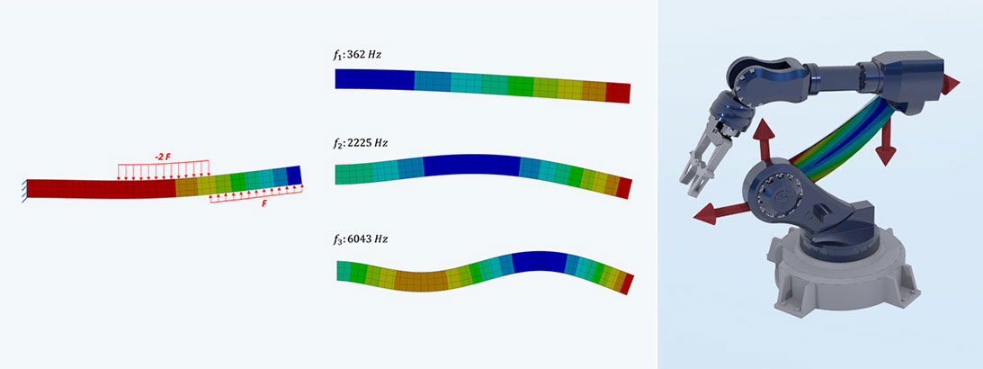
Functional principle of modal superposition | © CADFEM Germany GmbH
In the example of the beam, the first three bending modes are used to describe the deformation. The reduction allows the number of degrees of freedom to be reduced from 3800 in the FE model to 3.
To get to the solution, the reduced model is transferred to state space, whereby the following system of equations must be solved:

Here, the displacement solution y of a virtual sensor is determined based on the input u.

Illustration of the 4 state space matrices | © CADFEM Germany GmbH
How to export a reduced model from Ansys Mechanical?
In order to actually perform the reduction, you do not need to set up the matrices manually, nor do you need in-depth APDL knowledge. The SPMWrite command is accessible via a predefined APDL script, which you can integrate into your Mechanical project. This can be found in the Ansys installation path.
The basis of the export is a modal analysis that is supported in the same way as your future twin should be supported: If you support the left side of the bending beam fixed, it will not move in the twin either, but you will then also not have access to the reaction force, for example. Open DOFs are not a problem.

Embedding of the macro in Ansys Mechanical | © CADFEM Germany GmbH
Once the macro has been imported, you still need to assign 5 parameters to it: ARG1, 2 and 3 can be filled with the default value 0, ARG4 should be set to 1 in order to export the speed and acceleration as well as the displacement and ARG5 must be filled with -2 so that the full. SPM file can be written. Now you can solve the modal analysis and find the following file in the solution files: "file.spm". But how many modes should you set? The answer is quite simple: As many as you need to describe your model plus the number of rigid body modes, i.e. the number of open degrees of freedom.

Output File structure (file.spm) | © CADFEM Germany GmbH
Three inputs and outputs were used in the output file, but how does the tool know which variables must be measured or output at which points? The definition is done via remote points which are named according to the following scheme: input_<name>_ux for an input, or output_<name>_ux for an output, where ux is representative of the corresponding degree of freedom (alternatively: uy, rotx,...). In order to create several degrees of freedom at one location, a master remote point can be created to which the correspondingly named points are connected. If only inputs are used, a force input and a displacement output are created at the point (energy-conserving model).

To define several remote points at one location slaves can be connected to a master remote point | © CADFEM Germany GmbH
The reduced model can be combined with other components in the system simulation. In our example, the modal superposition cannot model large deformations and therefore the movement of the robot arm. If the components are reduced individually, the kinematics of the assembly can be modeled in the system simulation. Depending on the application, this can also be implemented by a clever choice of measurement technology, e.g. by measuring the cutting forces.

ROM in Ansys Twin Builder, the state vector is marked red | © CADFEM Germany, Model: AmirAli Orooji, GrabCAD
Can a digital twin output stress?
A common application of digital twins is strength assessment, e.g. for predictive maintenance applications or to determine the remaining service life during operation. But how do you get the stresses required for this? Let's first take a look at the inputs and outputs of our model: In addition to the pins we defined in Mechanical, the state vector can also be output. For each mode, we find a pin there that outputs a value that changes over time. These values form the modal coordinates, which represent the entire component behavior in an n-dimensional space, where n is the number of modes used.
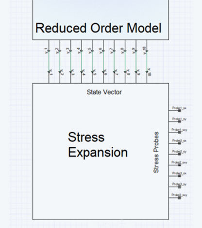
In order to understand its content, this state vector must be transformed back into the coordinates we are familiar with. It must therefore be expanded. To do this, an n x m matrix is exported from Ansys Mechanical, where n is the number of modes and m is the number of results to be expanded, this can be stresses, strains, displacements or nodal forces. Each result is a scalar quantity, which means that a very large number of results would need to be expanded for a complete stress plot, which is why virtual strain gages are usually used. This matrix must then be multiplied by the state vector to obtain a time history of each value.

Stress expansion, linked to the reduced model of the robot arm | © CADFEM Germany GmbH
What does a service life assessment look like in use?
The reduction of the mechanical system results in a very lightweight application that can also reliably determine stress results in real-time use. A downstream service life assessment is used to determine component damage from the stresses, which is also used to estimate the remaining useful life. This information can provide you with crucial support in efficiently planning the future maintenance of your products or in detecting damage at an early stage so that products can be recalled in a targeted manner.

Exemplary damage progression of the robot arm over a period of 100 days | © CADFEM Germany GmbH
Training on the topic
-
Structural Mechanics Simulation with Ansys Mechanical

This course is your introduction to structural mechanics with Ansys and the perfect foundation for all further Ansys Mechanical courses
-
System Simulation with Ansys Twin Builder

From the initial functional idea and schematic sketch to the simulation of your entire product with a system model.
-
Reduced Order Models for System Simulation with Ansys

Learn how to combine the accuracy of field simulation with the speed of system simulation for highly complex systems.


Editor
Dr.-Ing. Marold Moosrainer
Head of Professional Development
+49 (0)8092 7005-45
[email protected]
Cover images: Left: © CADFEM GmbH | Right: CADFEM Germany,
Model: AmirAli Orooji, GrabCAD
First published: February, 2024


