Strength Verification of Plastic Components According to VDI 2016
Dr. Matthias De Monte
12.06.2026
Practical example from the early concept phase using Ansys Mechanical
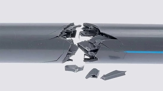
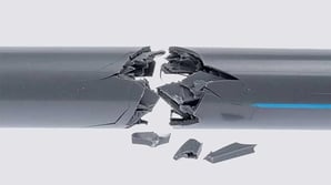
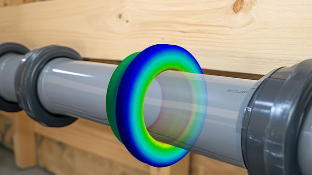
Will a plastic component really withstand an internal pressure of 3 bar at 80 °C over a service life of 30 years? Using a pipe coupling element as an example, this TechArticle demonstrates how strength verification according to VDI 2016—explicitly accounting for time and temperature effects—can already be performed in the early concept phase using FEM simulation in Ansys Mechanical.

Summary
- Strain-based strength verification according to VDI 2016: In addition to classical stress evaluation, the guideline enables a realistic assessment of the time- and temperature-dependent long-term strength of plastic components based on strain.
- Practical proof-of-concept example: A polypropylene pipe coupling element illustrates how Method C of VDI 2016, combined with FEM simulation in Ansys Mechanical, allows for fast feasibility and dimensioning assessments.
- Simulation as a decision-making tool: A conservatively calculated utilization of 117% reveals the need for design optimization at an early stage. After selecting a specific material, Method A confirms that the component meets the required long-term strength.
Strength Verification in the Proof-of-Concept Phase
To illustrate early-stage strength verification, a pipe coupling element for domestic indoor water piping is considered. The goal is a cost-efficient design, motivating the use of a thermoplastic material. In this early development phase, unreinforced polypropylene (PP) is assumed; the specific grade has not yet been defined. Manufacturing is planned via injection molding.
Operating conditions are defined as a system pressure of 3 bar, a maximum operating temperature of 80 °C, and a design lifetime of 30 years. The component is exposed only to ambient air and is not in direct contact with water.

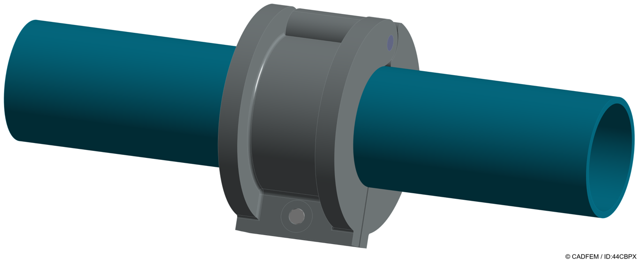
Pipe coupling element for indoor drinking water systems | © CADFEM / ID: 44CBPX
Strength verification is carried out in the proof-of-concept phase using Method C of VDI 2016. The objective is a fast feasibility and dimensioning assessment based on a simplified simulation—before selecting a specific material or detailed material data.
Method C represents the short- and long-term behavior of the polypropylene polymer class using analytical approaches and does not require material-specific stress–strain or creep data. Influences such as temperature, service time, and weld lines are considered via standardized factors.
Overview: What Does VDI 2016 Include?
The guideline VDI 2016 “Strength verification of plastic components” provides a standardized methodology for assessing structural integrity and long-term strength of thermoplastic components. It closes a gap left by classical metal-centered engineering methods, which are only partially suitable for plastics due to their pronounced time- and temperature-dependent behavior.
VDI 2016 distinguishes three calculation methods (A, B, and C), tailored to different phases of product development.
-
Method A: detailed nonlinear finite element analysis for final design validation
-
Method B: simplified simulation approach
-
Method C: deliberately conservative, highly simplified method for early proof-of-concept phases
A key feature of Methods B and C is the strain-based verification instead of a purely stress-based approach. This is crucial for plastics, as properties such as Young’s modulus change significantly with temperature and load duration due to creep. By comparing calculated equivalent strain with allowable material strain, VDI 2016 enables a more realistic long-term assessment and helps identify creep failure or excessive deformation early.

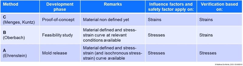
Overview of strength verification methods according to VDI 2016 | © Matthias De Monte, 2025 / ID: 6XEB19
Calculation of Equivalent Strain in the Component
For the strain-based verification according to VDI 2016, Method C, the governing strain in the component must be determined. Strains in the pipe coupling element are obtained via structural FEM simulation in Ansys Mechanical.
The model considers a screw preload preventing component opening as well as the internal pressure of 3 bar. Temperature is set constant at the maximum operating temperature of 80 °C, representing a conservative long-term scenario.
The Young’s modulus used in the simulation follows the workflow defined in VDI 2016, Method C, applying a time- and temperature-reduced modulus.

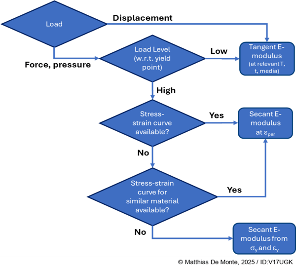
eper: permissible strain; sy: yield stress; ey: yield strain
Workflow for determining Young’s modulus (Method C) | © Matthias De Monte, 2025 / ID: V17UGK
The simulation uses a linear-elastic material model with a tangential modulus adapted for 30 years of service at 80 °C. The FEM parameters are EFEA = 140 MPa and νFEA = 0,50. The governing quantity in Method C is the maximum positive principal strain. Under an internal pressure of 3 bar at 80 °C, a maximum principal strain of 1.94% occurs in the hinge opening area. Due to the design, a weld line is conservatively assumed at this critical location in the early development phase.

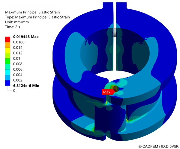
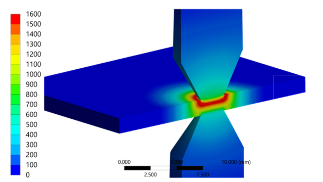
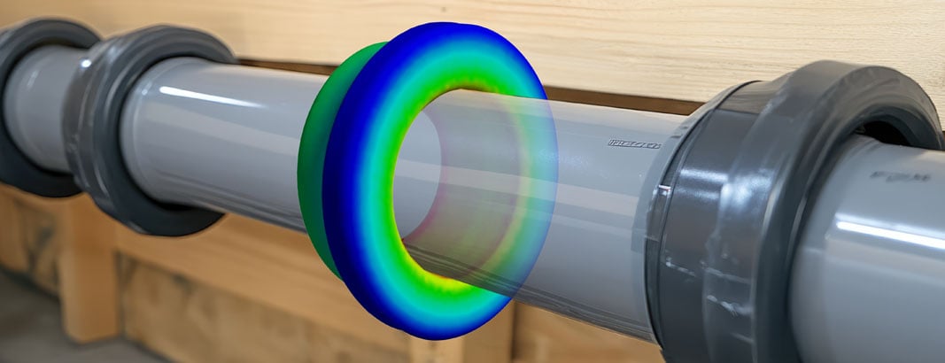
Maximum elastic principal strains under 3 bar and 80 °C | © CADFEM / ID: DI5V5K
Calculation of Allowable Strain and Utilization
For strength verification according to VDI 2016, Method C, the allowable strain is the decisive comparison value. The starting point is the material-specific limit strain describing the onset of micro-damage. According to VDI 2016 Part II, it can be determined from tables or derived from Young’s modulus at 23 °C. For polypropylene, a limit strain of 2.33% applies. This limit strain is reduced by relevant influence factors, particularly service time, operating temperature, and weld lines. The time- and temperature-dependent interaction is represented by the material-specific interaction factor m = 2.3 for PP. A reduction factor of CC,nb = 0,85 is applied for the weld line; media influence is neglected due to the absence of water contact. With a safety factor SC = 1,2, the allowable strain results in εₚₑᵣ = 1,66%.
The utilization aC is defined as the ratio of equivalent strain to allowable strain at the critical location. The safety factor is already included; aC < 100% indicates sufficient strength. For this load case, Method C yields a maximum utilization of 117%.
This exceedance is not a numerical inaccuracy but reflects the deliberately conservative nature of Method C and provides a clear decision metric in the early concept phase.
In later development stages, optimized gate design can avoid weld lines in highly stressed areas. Moreover, Method C does not consider material-specific creep strength. Applying Method A, which includes real creep data for a specific PP grade, reduces utilization to 94%, thus fulfilling the strength requirement.

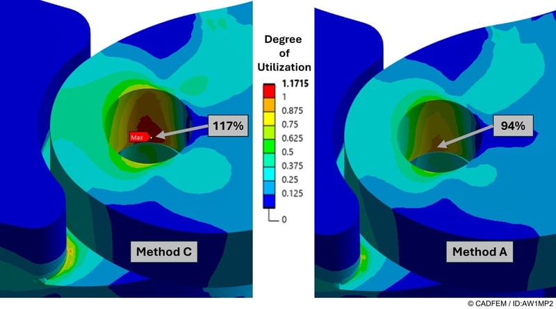
Utilization according to VDI 2016 using Method C and Method A | © CADFEM / ID: AW1MP2
Strength Assessment for Plastic Parts with Ansys According to VDI 2016
Learn how to design plastic parts safely using Ansys Mechanical and VDI 2016 – fast, systematic, and practice-oriented. This training is offered as a 1-day course.
From Pipe Coupling Example to Safe Everyday Design
The polypropylene pipe coupling example clearly illustrates how VDI 2016 enables robust engineering decisions already in early development phases. Method C deliberately serves as a conservative filter to identify critical regions at an early stage—such as the hinge opening with a potential weld line in this case. The subsequent transition to Method A then allows for a targeted, material‑specific assessment without unnecessarily over‑dimensioning the component. This approach can be directly transferred to a wide range of thermoplastic component applications where temperature, service time, and creep behavior are decisive design factors.
The author of this article is Dr. Matthias De Monte, Senior Expert and responsible for Design for Reliability in the Bosch business sector Cross Domain Computing Solutions. In this role, he is responsible for the design and validation of plastic‑based components for driver assistance and control systems subjected to thermal, mechanical, and time‑dependent loads. His technical focus lies in the fatigue, creep, and aging behavior of polymer materials. As a member of the Bosch‑wide Center of Competence for Plastics, he regularly contributes this industrial perspective to CADFEM training programs—both in the training on the strain-based strength verification according to VDI 2016 described here, and through complementary courses: Assess the fatigue life of plastics.
This article cannot and should not replace a training, but is intended to provide a practical introduction to strain-based strength verification according to VDI2016. Engineers who want to apply this methodology with confidence, avoid typical modeling and evaluation pitfalls, and systematically transfer the presented approaches to their own components can deepen their expertise in the CADFEM seminar Strength assessment for plastic parts with Ansys according to VDI 2016, which is taught by Dr. Matthias De Monte himself.
More on the Topic
-
Strength Assessment for Plastic Parts with Ansys According to VDI 2016

Learn how to design plastic parts safely using Ansys Mechanical and VDI 2016 – fast, systematic, and practice-oriented. This training is offered as a 1-day course.
-
Assessing the Fatigue Life of Plastics

In this training, you will learn how to assess and apply various concepts for fatigue and creep fracture loads on plastic components. This training is offered as a 2-day course.