Design of asynchronous machines with Motor-CAD

E-machines are ubiquitous when it comes to converting electrical energy into motion and vice versa. Among the many types of e-machines, the asynchronous machine (ASM) is one of the most important and widespread machine types. Precise design is therefore an important task. This can be realized multiphysically with Ansys Motor-CAD.

TechArticle_asynchronous-machine_Header-2

ASM vs. PMSM: What is actually the difference?

There are two types of machines that have become established for electrical machines: Synchronous machines and asynchronous machines, also known as induction machines (IM). The most common type of synchronous machine is the permanent magnet synchronous machine (PMSM). In the PMSM, the rotor rotates synchronously with the rotating field of the stator; in the IM, the rotor rotates at a slightly different speed. This slip results in fundamentally different operating characteristics. While PMSMs are well suited to getting a lot of power and torque out of a small installation volume and are generally more efficient than IMs, IMs are cheaper to manufacture and easier to control.

The differences mentioned above result in slightly different areas of application. Synchronous machines are used as generators in power plants and usually also in wind turbines. Furthermore, they are installed in servomotors and in some industrial drives. Induction machines are also used in numerous industrial drives, i.e. in traction drives, often as linear drives. Both types of machines are also currently used as the main drive in electric vehicles and electric trains.

TechArticle_asynchronous-machine_Generators-with-turbines

Generators with turbines for conventional power plants | © Adobe Stock

Special features of the design in Motor-CAD

The induction machine is therefore of interest if you need an inexpensive, robust and easily controllable machine and have some leeway in terms of installation space. Due to the slip in IM, the two machine types are designed differently. PMSMs can also be designed directly with 2D FEM at an early design stage. The calculation time is manageable, as a steady state can be reached quickly. With IM, however, the situation is different. This type of machine depends on the eddy currents in the rotor cage, the calculation of which is very time-consuming. As a result, IM is first designed analytically and then the results are both verified and the design is optimized numerically.

Furthermore, electrical machines are generally an application that cannot be considered purely magnetically. At the very least, the torque equation and thus the introduction of a relationship between the electrical terminal variables and the mechanical variables of torque and speed is necessary for the design. As soon as this design phase has reached a certain level of maturity, questions about other physical domains arise. For example, electrical machines heat up significantly despite an efficiency of often over 90%. Active cooling by fans or liquid cooling are not uncommon.

TechArticle_asynchronous-machine_Multiphysical-simulations-Motor-CAD

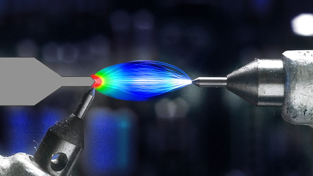
Multiphysical simulations in Ansys Motor-CAD | © Ansys Inc.

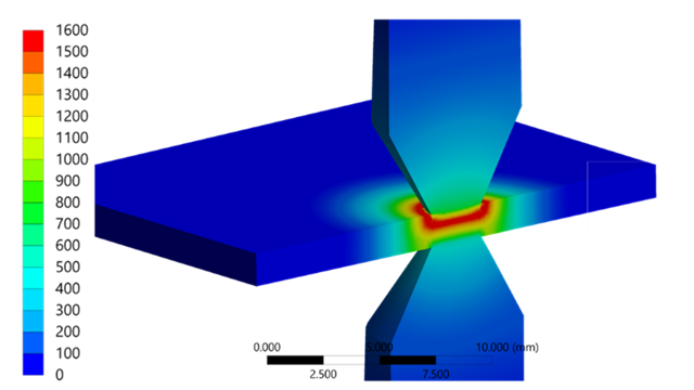
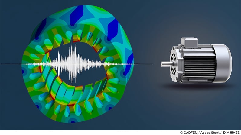
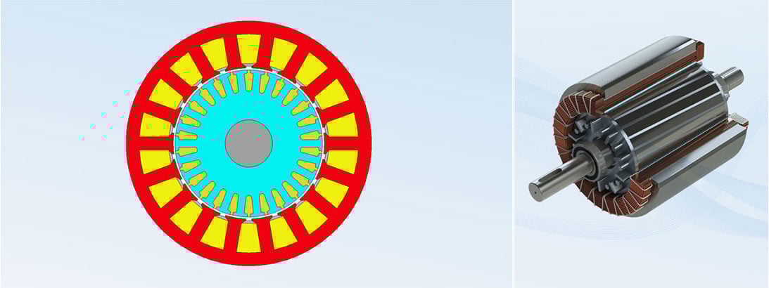
Rotor strength - will the squirrel cage hold or will the short-circuit bars be torn outwards? - or acoustics are further points that must also be taken into account. Ansys Motor-CAD provides the possibility to answer all these questions directly in one tool. The critical points for thermal, rotor strength and acoustics differ between synchronous and asynchronous machines. For example, the hotspot in synchronous machines is usually found in the stator winding, whereas in induction machines it is often the cage rotor. Here, high eddy currents cause the cage to heat up considerably, which is why copper is sometimes used as the cage material.

The equivalent circuit model of the IM

The analytical calculation of the induction machine is not necessarily a disadvantage, because analytical calculations are still much faster than numerical simulations. The challenge here is rather to understand the very detailed analysis of the IM, which has been developed over 100 years ago, so that the corresponding calculation programs can be both used and interpreted correctly. With Ansys Motor-CAD, we have a hybrid tool that can calculate the IM analytically in many respects and also offers a numerical simulation for the detailed design.

The so-called T equivalent circuit model (T-ECM) is used as an analytical approach: An electrical network that can be described with two mesh equations and one node equation. If the equivalent circuit elements, resistances and inductances are variable, any operating points can be calculated. The left-hand side of the equivalent circuit diagram represents the stator with its stator phase resistance R1 and the stator leakage X1. The stator leakage is to be understood here as the sum of all leakage components on the stator side. It therefore includes the stator slot leakage and the winding head leakage. The main inductance (Xm) describes the magnetic coupling between the stator and rotor fields.

TechArticle_asynchronous-machine_Equivalent-circuit-model

Equivalent circuit model of an induction machine | © CADFEM Germany GmbH

As the stator and rotor windings are electrically isolated, there should also be two circuits in the ECM. To simplify the calculation, the rotor sizes are therefore converted to the stator. The stator winding number w1 and the rotor number of turns N2 are used as the conversion factor ü in relation to the base field. These values are interpreted as the effective number of turns. The whole process is therefore similar to a gear ratio, only electrical.

TechArticle_asynchronous-machine_conversion-factor

The rotor stray inductivity X2 and the rotor resistance R2, here split into two parts, are multiplied by this factor. An extension already included is a resistor to take into account the iron losses RFe in the ECM.

Operating behavior at single load point

One of the results determined with this ECM is the torque-speed characteristic curve, which is obtained for different loads when operating on a rigid grid. Here you can quickly see which rotor speed and therefore which slip leads to the highest torque. In synchronism, i.e. the absence of a relative speed between the stator field and the rotor, the machine does not transmit any torque, as no eddy currents can be induced in the rotor that could build up a rotor field, which in turn would be necessary as the counterpart to torque formation. This results in no-load operation and the characteristic curve intersects the X-axis.

TechArticle_asynchronous-machine_Torque-speed-characteristic

Torque-speed characteristic of an asynchronous machine | © CADFEM Germany GmbH

In the past, when electric machines were primarily designed for one operating point, the so-called rated load point, attempts were made to select the design in such a way that the maximum efficiency of the machine was achieved as far as possible under the expected load. This maximum is always close to the maximum of the torque-speed characteristic shown above, the breakdown point. The machine is therefore operated on the mains between the breakdown point and the noload point. The majority of the curve therefore describes unstable behaviour. Today, however, e-machines are increasingly used at different speeds (e-cars, wind turbines, conveyor belts, etc.)

Efficiency and other variables in the M-n map

This requires an inverter. With it, the machine is always operated at the maximum of the characteristic curve, but the frequency is adapted to the current supply. It is possible to generate an entire torque-speed map (M-n map). Ansys Motor-CAD offers solutions for directly "translating" your own machine configuration into a map; and not just for IM and PMSM, but for all common machine types. A comparison between IM and PMSM quickly shows in which areas which machine type is superior. This raises the question of which area of the map is actually relevant for the application.

TechArticle_asynchronous-machine_Schematic-efficiency-map

Schematic efficiency map of an IM (left) and a PMSM (right) | © CADFEM Germany GmbH

The figure on the left shows a typical efficiency map of an IM; on the right we see the counterpart for a PMSM. It can be seen that IMs tend to be less efficient than PMSMs at low speeds. However, their maximum efficiency extends up to the maximum speed. The speed at which the machine can no longer deliver the maximum torque is called the corner speed. The field weakening range begins to the right of this. Since IM and PMSM behave fundamentally differently here, this also results in a different drop in the limit characteristic curve. With PMSM, the limit characteristic falls with 1/n, thus decreases hyperbolically with the speed. This is quicker with IM, namely with 1/n2.

Simulating maps - considering driving cycles!

We therefore need information on the load profile or on a driving cycle in which the engine should achieve the highest possible efficiency, for example. For e-cars, the WLTP (Worldwide harmonized Light vehicles Test Procedure) driving cycle is a good approach for designing a motor for an e-car. If the torque requirement for certain speeds is derived from the speed-time diagram and an assumed vehicle model (cw value, mass...), this results in the point cloud shown in the M-n map. This makes it clear that the aim of the design in variable operation is to position the area of maximum efficiency as well as possible so that most of the operating points of the driving cycle lie within it.

To achieve this, many iterations with fast software are necessary. If you then understand the physics, which tells you, for example, that wider slots in the stator allow more turns to be installed in the winding and can therefore increase the stator field, but at the same time the stator teeth become narrower, which causes them to saturate more quickly and this effect can be seen in a larger stator stray loss in the equivalent circuit diagram, then with a little experience you can quickly simulate an optimum machine. This has the following effect on the characteristic diagram.

TechArticle_asynchronous-machine_Efficiency-map

Efficiency map of an IM with unchanged (left) and reduced stator teeth (right) | © CADFEM Germany GmbH

An example: On the left hand side an efficiency map of an ASM with original geometry is shown, on the right with 30% narrower stator teeth. It can be seen that the range of high efficiencies is widening towards higher torques. This improves the efficiency of some of the WLTP operating points shown in blue. This sounds very positive at first, but the thermal solver also provided in Motor-CAD reveals that the thermal behavior deteriorates significantly. It turns out that a multi-physical approach via simulation is essential in order to design an asynchronous machine taking all parameters into account - and fortunately this is also possible thanks to Motor-CAD.

Training on the topic

Author

Peter Dück

CAE Engineer

+49 (0)8092 7005-757
pdueck@cadfem.de

Editor

Dr.-Ing. Marold Moosrainer

Head of Professional Development

+49 (0)8092 7005-45
mmoosrainer@cadfem.de

Cover images: Left: © CADFEM GmbH | Right: © Adobe Stock
Published: May 2024