Smart models in Ansys instead of dead geometry

Unnecessarily rigid CAE workflows slow down simulation. When every geometry change triggers manual update loops to fix references, the process becomes time-consuming, error-prone, and frustrating. Yet Ansys Workbench offers the possibility to design models flexibly using parameters. But how can one systematically get started with parametric models - especially for geometries?

Blog_TechArticle_DSO_Parametrisierung_Header
Simulated cooling channel in an e-machine | © Adobe Stock/CADFEM Germany GmbH

Why do we even want to parameterize?

Do you know this situation? After the first simulation, extensive changes are required. When updating the geometry, painstakingly defined boundary conditions, material assignments, or contacts are lost. Particularly frustrating if you previously carried out elaborate defeaturing to prepare the CAD model for simulation. Every further geometric modification then means time-consuming manual work and potential sources of error.

Parameterization provides a remedy here. It allows geometry changes to be implemented efficiently and consistently. Instead of manually editing each update in the CAD system and then updating the simulation model, you simply modify defined parameters, and the model automatically adapts. This saves time, reduces errors, and makes the entire process more robust. In this way, you move away from “dead” geometry towards smart models - a step that pays off quickly, especially across multiple development stages.

These intelligent geometries enable systematic optimizations, sensitivity analyses, and automated CAE workflows. This increases the traceability of design decisions and accelerates product development. In short: parameterization lays the foundation for efficient and future-proof simulation processes. In this article, we provide an overview of the possibilities of geometry parameterization within the Ansys ecosystem - including typical pitfalls. Using two practical examples, the housing of a windshield wiper gearbox and the cooling channels of an e-motor, we demonstrate how geometry parameterization can be applied.

Blog_TechArticle_DSO_Parametrisierung_cad_animation_loop

Component: Windshield wiper housing with multiple variants | © CADFEM Germany GmbH

Bi-directional integration with other CAD tools

Many CAD systems such as Creo, Catia, Inventor, or Siemens NX offer extensive options for parametric modeling. Through the bi-directional CAD interface  , such models can be directly integrated into Ansys Workbench. When you change a parameter via the Parameter Set in Ansys, the CAD tool installed on your system is used to update the geometry. The prerequisites for using this feature are a successful configuration of the interface via the CAD Configuration Manager (administrator rights required) and a valid license for your CAD interface.

For our example, we first load the gearbox housing into a geometry cell in Ansys Workbench. In order for Workbench to recognize the parameters  , they must be uniquely named in the CAD system. This can be achieved with a prefix in the parameter name, such as “ANS_”. The prefix can be checked and adjusted in the “Properties” window, as shown in the figure. But where do our parameters appear? They show up in Ansys Mechanical in the structure tree  under the respective bodies in the Details section. By ticking the checkbox, a small “P” appears. This allows you to specifically control lengths, angles, or other dimensions and vary them in studies via the Parameter Set.

Blog_TechArticle_DSO_Parametrisierung_Workbench-Details-Parameter-Identifier

Workbench details showing parameter identifiers, Mechanical details showing parameters | © CADFEM Germany GmbH

History-based vs. Direct Modeling

History-based modeling is the standard in many CAD systems. The model is created step by step, with all features documented in the model tree. At the top, for example, is the first sketch, which is then extruded, followed by additional details such as holes, ribs, etc. Let’s take a look at the feature history of the gearbox housing. A detail such as the rib pattern can be selected and adjusted via parameters such as the number, thickness, or angle of the ribs. This structure is powerful, but it requires a well-thought-out strategy for model construction: What dependencies exist? Will references remain stable when changes are made? In particular, the order of features can be decisive in determining whether modifications work as intended.

Blog_TechArticle_DSO_Parametrisierung_Creo-Feature-Historie

Creo feature history with parameterization option | © CADFEM Germany GmbH

Ansys Discovery, the current standard modeler from Ansys, uses a different approach: so-called Direct Modeling. This method does not rely on a feature history, so that parts, surfaces, and curves are listed in the structure tree. Instead, you work directly on the existing geometry - ideal for quick defeaturing and flexible adjustments. For example, small features such as fillets, chamfers, or logos can simply be removed from the geometry. This makes simulation preparation particularly efficient. Or you can pull and move surfaces or bodies if you want to test geometric changes in the simulation without modifying the original geometry.

Parameters can also be defined in this Direct Modeling workflow. In the animation, you can see how the Pull operation is applied to an existing hole. A text field appears that allows you to enter a new diameter. Right next to it is the icon used to create a parameter, which can then be controlled via the parameter menu. To move or pull surfaces by a defined value, a dimensioning function is available. With the Move tool active, a reference point can be set via the “Ruler” to precisely control the measurement. This makes it possible to “retrofit parameterization” for manageable changes in otherwise static geometry.

Parameterization in Direct Modeling | © CADFEM Germany GmbH

History Tracking in Ansys Discovery

What if you don’t have a CAD interface but still want to model in a history-based manner? Or what if your CAD model was not originally designed with a focus on parametric variation? For these cases, Ansys Discovery offers the History Tracking mode. This creates a feature history similar to that of traditional CAD systems. But be careful: switching back to Direct Modeling is not possible - the history will be lost. Therefore, it pays to have a strategy for model construction before starting with tracking. A practical feature is that after loading a geometry, it automatically forms the first “block” - no need to start from scratch. We demonstrate this with the example of a motor cooling.

The base geometry of the motor is complex (windings, bearings, etc.), but the focus here is on the cooling jacket. Therefore, with History Tracking enabled, the base model (.step) is loaded first. Next, the prepared section of the cooling channels is modeled. Each editing step is saved as a block and remains editable. First, surfaces are created in the empty pocket, which then form channels through an offset pattern. Within these blocks, values such as the spacing and thickness of the ribs can be parameterized. It is even possible to define dependencies between created parameters - for instance, the spacing in the pattern can be derived from the available length, width, and the number of channels.

Blog_TechArticle_DSO_Parametrisierung_History-Tracking

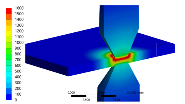
History Tracking bei einem wassergekühlten Elektromotor | © CADFEM Germany GmbH

Sketches created during History Tracking can also be parameterized. Using the sketch icon, you can switch into the sketch and edit it at any time. To make dimensions available outside the sketch within the block, dimensions must be defined in the sketch. After editing, these dimensions appear in the block and can then be used as parameters. Dimensions that are not defined remain hidden within the blocks. In addition, constraints can be applied in sketches to enforce conditions such as parallelism, coincidence, or tangency.

Blog_TechArticle_DSO_Parametrisierung_Parametrisierung-Skizzen

Parameterization of sketches in History Tracking | © CADFEM Germany GmbH

Key considerations for geometry parameters

The choice of the right method depends on the goal: for complex geometries, a history-based approach with a clear construction strategy is recommended. For simple variants, Direct Modeling is often sufficient. Therefore, make sure to carefully consider in advance which dimensions should remain variable and where your focus for model variants should lie. Especially at the beginning, it can be useful not to fully parameterize every detail of your parts, but instead to start with a limited selection of parameters. This helps to better understand the basic functions and approaches and to identify potential pitfalls. No time to dive in on your own? Then our Discovery Modeling training is just what you need!

Conflicts, however, are usually unavoidable when dealing with complex models and generously varied parameters. That’s why you should check the min/max values for each parameter early on, directly during modeling. By defining limit values in the CAD system, you can ensure that individual features do not extend beyond part boundaries, create unwanted overlaps, or result in impractical geometries. To test the simultaneous variation of all parameters before running a sensitivity analysis or optimization, it is recommended to carry out a geometry pre-check in advance. We discuss how to put this into practice in our CADFEM Let’s Simulate session on parameterization.

Extra tip: Use named selections for robust assignment of boundary conditions. This way, surfaces and contacts remain consistently identified even after geometry changes - an essential factor for stable simulation models. If boundary conditions, meshing settings, etc.  are assigned via graphical selections, the topology may no longer match after a geometry update. The notorious question mark then appears in Ansys Mechanical, and you, the user, are left to reassign everything manually. That’s why you should take advantage of the option to define named selections directly in Discovery or your CAD interface and use them in the simulation model.

Blog_TechArticle_DSO_Parametrisierung_Named-Selections

Named selections in the final parameterized electric motor | © CADFEM Germany GmbH

Outlook: Even more control

What if all this still isn’t enough and you want even more control? For those who need greater flexibility, Ansys Discovery also supports scripting. Behind each history block there are small Python snippets running in the background. Don’t worry - you don’t need to understand or write them yourself. But it does mean that a Python interface is provided. We can use this to prepare geometry via scripts or even build it completely from scratch - ideal for custom logic and automation. This may sound terribly complicated at first. But it’s not at all, as you can read in another CADFEM TechArticle.

Thanks to smart geometry in the simulation process, adapting to new variants is no longer a problem. But how can we now exploit the full potential of intelligent geometry to systematically explore the design space, instead of tediously comparing just a handful of variants? Through automated process chains, any solver and evaluation can be linked, making it possible to efficiently compare variants with respect to their results. Want to dive deeper? The foundation is already in place thanks to smart CAD models! Our CADFEM Let’s Simulate series provides practical insights on how to use parametric models in optiSLang for design studies and optimizations.

Blog_TechArticle_DSO_Parametrisierung_Optimierung-Kuehlkanal

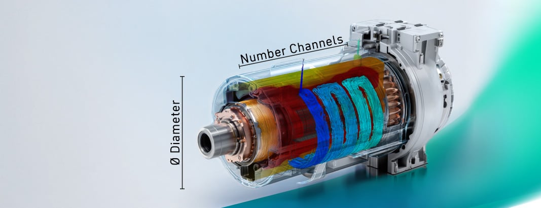
Optimization of the cooling channel with Ansys optiSLang | © CADFEM Germany GmbH
geometry-preparation-in-ansys-discovery-18119


Tip

Geometry Preparation in Ansys Discovery

Whether you work with Ansys Discovery or Ansys SpaceClaim, this training will teach you everything you need to know about modeling for Ansys.

More information and registration

Ansys Fluent GPU Performance Testing – Use Case

Ob im Maschinenbau, in der Luftfahrt oder bei der Produktentwicklung: Strömungssimulationen sind für präzise und schnelle Entwicklungsprozesse unerlässlich. Doch wie unterscheiden sich CPU- und GPU-basierte Simulationen, und was sind die wichtigsten Kriterien bei der Hardwarebewertung? Dieser Beitrag beleuchtet grundlegende Unterschiede, Leistungsmetriken und die Anwendungsmöglichkeiten von GPU- und CPU-Setups für Ihre CFD-Projekte.t

Use Case entdecken

Teaser_24_18_GPU_640x360_AdobeFirefly

Training on the topic

Portrait_DSO_Blog-1

Author

Daniel Soukup

Solution Architect

+49 (0)8092 7005-330
dsoukup@cadfem.de

Portrait_JNE_Blog

Editorial

Dr.-Ing. Jörg Neumeyer

CAE Engineer

+49 (0)8092 7005-766
jneumeyer@cadfem.de