Meshing – Connecting geometry and the solver

Ideally, we want to input the geometry and output the results. However, due to complexity, we must rely on numerical solutions. The discretization of the fluid domain is critical, and the aim is to balance accuracy and computational costs. In this article, we present how Ansys Fluent meshing offers a clear and flexible workflow for creating high-quality computational meshes for complex geometries.

TechArticle_CFD_Vernetzung_Teaser

Why do we need a good mesh?

The goal of any simulation is to represent reality as accurately as possible. The prerequisites for this are a powerful solver, the correct choice of flow models, and appropriate discretization methods with minimal numerical diffusion. However, one essential point is often forgotten: the computational mesh. A good computational mesh is always the foundation for reliable results in CFD. Ansys offers a variety of different meshing tools such as Ansys Meshing, TurboGrid, ICEM CFD, and Fluent Meshing. Since we work with Fluent Meshing for the most part in our day-to-day calculations and because it is particularly suitable for meshing complex geometries, we will look at some of its functionalities and settings, using the example of a chute.

Chutes, like the one used here, are often found in hydraulic laboratories and are used to study overflow behavior. In this case, the water level in the upstream section is of particular interest. The weir structure has a height of 400 mm, a thickness of 75 mm at the top, and features a small radius of 25 mm and a large radius of 200 mm. The requirements for the mesh, therefore, include both the accurate representation of the geometric features of the chute and the resolution of large gradients in the flow domain. This specifically concerns the gradient of the phase fraction (water surface) as well as the velocity gradients near the walls and in the downstream section. 

Fluent Meshing offers two predefined, customizable workflows: The Watertight Meshing (WTM) and the Fault Tolerant Meshing (FTM) Workflows. The latter is specifically designed for faulty, "leaky" geometries, where geometric preparation is time-consuming or even impossible. The key distinguishing feature regarding the geometry is the so-called watertightness. The WTM Workflow can be used whenever you can imagine water being poured into the geometry without leaking out anywhere. Since our chute meets this requirement, we are using the WTM Workflow here.


TechArticle_CFD_Vernetzung_Workflow

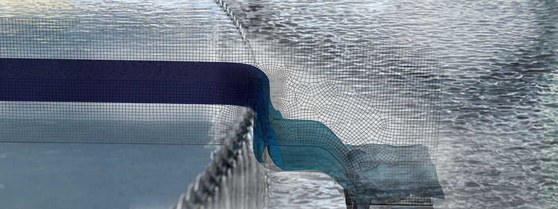
Comparison of the workflow with geometry and final free surface  | © CADFEM GmbH 


From surface to volume mesh 

By selecting the WTM Workflow, a process is defined with specific steps to be completed in sequence. The basic procedure consists of importing the geometry, creating a cell size distribution, meshing the surface, and then generating the volume mesh. Note: Throughout the workflow, assignments can either be made through direct geometry selection, a search function, or via "wildcarding." The advantage of wildcarding is that it saves the search query itself, not just the result; for example, using *wall* will always select all boundaries with wall in their name.

When importing the geometry, it is translated in the background into a tessellated representation, the pmdb. Using Add Local Sizing and the settings under Generate the Surface Mesh, the so-called size field is "fed" with information regarding local cell sizes. You can imagine this size distribution like a temperature field: the cell growth corresponds to thermal conductivity, and local refinements correspond to heat sources. Settings such as Local Refinement Region or Face Sizing allow for cell size adjustments that decrease with increasing distance. Note: The size of the resulting cells is visualized as a small red cube when clicking into the respective input field.

Under Describe Geometry, you must specify whether the imported geometry consists of a pure fluid region, a pure solid region, or a combination of both. Depending on the selection, Fluent adds further sub-steps to the workflow. For instance, it is possible to create the negative volume from an imported solid geometry by closing boundaries. In our case, the flow geometry is already defined, and we do not want to mesh any solid geometry. Therefore, the Only Fluid option is sufficient. Update Boundaries and Update Regions are used to assign the type of boundary condition or volume body: Is it a wall or an inlet? Is the volume a solid or a fluid?

TechArticle_CFD_Vernetzung_Vergleich-Definition_1

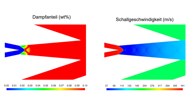
Comparison of a local refinement based on a surface and a local refinement region | © CADFEM Germany GmbH 


CFD-1


Ansys CFD

Make fluid flows visible with Computational Fluid Dynamics (CFD).
Analyze particle and material flows with Discrete-Element-Method (DEM) and SPH (Smoothed-Particle Hydrodynamics).

Request trial version

How to fill the domain?

To resolve the high gradients at the wall, a predefined number of prism layers – known as boundary layer elements – are generated in the wall-normal direction. The control of these elements is managed through four degrees of freedom: ‘height of the first layer’, ‘number of layers’, ‘growth rate’ and ‘height-to-width ratio of the last layer’. The selection of which degrees of freedom to specify depends on the type of definition used. For most applications, we recommend the Last Ratio type, as it allows for control over both the thickness of the first layer and the transition into the volume mesh.  

The local cell size of the volume mesh is controlled by the previously described size field. Initially, the available element types are tetrahedra and polyhedra. Due to the better cell quality, we always recommend using polyhedra, provided that all models are compatible with this type. Both types can be combined with a Cartesian hexahedral mesh, known as the Hexcore mesh. The tetrahedra or polyhedra then serve merely as a transition layer from the domain boundaries to the Hexcore mesh. Note: The 1:8 jump in cell size when using hanging nodes within the Hexcore mesh can be avoided by selecting the Avoid 1/8 Transition setting.

The assessment of mesh quality is typically based on two criteria. The first criterion pertains to the shape of the cells and their arrangement relative to neighboring cells: the Orthogonal Quality. If this value falls below 0.1, one can expect poor convergence and inadequate result quality. Improvements to the mesh can be achieved either through geometric adjustments or by using the optional task Improve Volume Mesh. The second criterion is the discretization error. This measures how much the result deviates from what would be achieved on an infinitely fine mesh (Richardson Extrapolation). Meeting the first criterion is a prerequisite for evaluating the second. 

TechArticle_CFD_Vernetzung_Netzvarianten

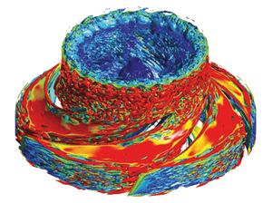
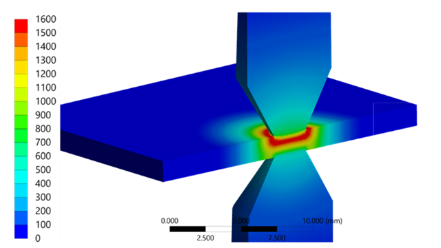
Example volume meshes covering the full fluid domain | © CADFEM Germany GmbH

How can the mesh be optimized?

Structured meshes have certain advantages over unstructured meshes in terms of mesh quality, but they are more challenging to create for complex geometries. Fluent offers the MultiZone Meshing capability, which allows for the automatic generation of a structured mesh, provided that a suitable topology can be found for the given geometry. The example geometry of the chute is particularly well-suited for this because it has a constant cross-section when viewed from the side. The source and target surfaces specified in the MultiZone task are the two glass walls of the chute. The final steps before generating the volume mesh include determining the element size in the extrusion direction and defining the prism layers. 

Except for the area near the two glass walls, the flow pattern in the longitudinal sections that run parallel to the glass walls differs only slightly. Accordingly, it is legitimate to simplify this to a 2D problem, which drastically reduces the computational effort. As of version 2024R1, Fluent Meshing has a workflow (beta) for creating 2D meshes that can then be read in by the Fluent 2D solver. Reducing the problem to a 2D problem makes it possible to efficiently analyze many different variants in a short period of time.

TechArticle_CFD_Vernetzung_Workflow-MultiZone1

Workflow zur Erstellung einer MultiZone und Detail der erzeugten Grenzschicht | © CADFEM Germany GmbH 


What’s next?

The local flow field should typically not depend on the location of the inlet or outlet boundary condition. If these boundary conditions are too close to the area of interest, it is not always necessary to adjust the geometry. By right-clicking on the task for generating the volume mesh, an extrusion can be added. This allows boundaries to be extended similarly to the MultiZone approach, enabling efficient analyses regarding the distances of the boundary conditions from "the area of action."

A single mesh is not enough! Only by comparing it with other finer meshes can the discretization error be estimated and the mesh independence of the solution demonstrated. Refinements are necessary where high gradients occur in the solution. In the example presented here, alongside the overflow area, the water surface is such a region. One possible approach for the overflow area is to define a Body of Influence, within which a maximum cell size can be specified. 

The position of the water level is typically unknown or varies depending on the different discharges or waves being analyzed. For cases of this kind, solution-based mesh adaptation is an efficient approach. Here, Fluent adapts the base mesh in such a way that the mesh is automatically refined in areas of high gradients and is not changed in the remaining areas. Thus, in the case of the water surface, a fine mesh is always generated where the phase boundary is located. This allows an efficient use of additional cells based on the current results of the simulation. Try it out! Also visit our seminar on meshing in Ansys Fluent.

Training on the topic

Autor

Roman Gabl

Engineering Services

+43 (1)587 707312
roman.gabl@cadfem.at

Editor

Malte Küper

Engineering Services

+43 (0)512 319056-23
malte.kueper@cadfem.at

Technical editorial:
Dr.-Ing. Marold Moosrainer
Head of Professional Development
+49 (0)8092 7005-45 | mmoosrainer@cadfem.de

Cover image: © CADFEM Germany GmbH / Adobe Stock