The FEM mesh of the future - mastering complexity, automating the mesh!

Meshing is a key step in the finite element method (FEM) for achieving accurate simulation results. From theoretical principles to practical strategies and advanced options such as curvature and proximity, this text highlights the importance of mesh quality, efficiency and customization to specific tasks. To demonstrate the ease of use, we perform the meshing process on a real and complex geometry of an engine block.

Blog_TechArtikel_Vernetzung_Header
© CADFEM Germany GmbH

Meshing in theory

To understand why we pay attention to good element quality, small aspect ratios and low distortion, let's take another look at the background. We are usually interested in displacements, strains and stresses. In three-dimensional space, this results in 15 unknowns, which require just as many equations. These are provided by continuum mechanics. But here we quickly reach our limits: The time required is enormous and analytical solutions are often not available. Anyone who has ever worked their way through pages of calculations involving the Airy stress function for a plate with a hole is all too familiar with these challenges.

Blog_TechArtikel_Vernetzung_Kontinuumsmechanik-FEM

Transition from continuum mechanics to FEM | © CADFEM Germany GmbH

But numerics also presents challenges. Three important points here are mesh fineness, shape functions and element quality. In FEM (structural analysis), systems of equations must be solved whose size depends directly on the number of elements and nodes. The computing time increases more than quadratically - therefore the following applies: "as fine as necessary, as coarse as possible". Some variables are calculated at the nodes (e.g. displacements), others are calculated in the element at the Gaussian points. Nodal quantities are directly represented by the degree of the shape functions. For other quantities (e.g. strains), the "resolution" is reduced via the derivation. This is why different result quantities require different mesh refinements!

The integration of the equations at element level is carried out using Gaussian integration. The more the real element deviates from the unit element, the less accurate the results will be. With distorted elements, non-constant Jacobian determinants arise, which lead to fractionally rational functions in the integral. As Gaussian integration is not exact for such functions, the demand for a "beautiful" mesh is also numerically justified. Uniform, structured meshes are more aesthetically pleasing and such meshes are often numerically better. If a mesh sends shivers down your spine, it is probably also bad for numerics. Because: "A beautiful mesh is often also a good mesh."

Blog_TechArtikel_Vernetzung_Gauß-Integration-FEM

Gaussian integration in the FEM | © CADFEM Germany GmbH

Meshing in practice

Let's move on to the practical part of the task and finally mesh. In my experience, despite all the automatisms, it makes sense to think first and then mesh. Meshing is part of our simulation tool and has certain tasks to fulfill. Which tasks? And to what degree of accuracy? Until the day when we no longer have to worry about computing capacity, efficient meshes need to be adapted to the task at hand! The counterbalance to computing time, however, is engineering time. Efficient simulation can therefore mean working with an automatically generated mesh that is slightly too fine. We save defeaturing and meshing time (working time) and let the computer calculate a bit longer.

Here I have the freedom to choose. Do I want to automatically mesh my models with a few basic settings and eliminate as many analyses as possible? Or do I mesh over 2-3 steps in an iterative process? I will briefly explain my iterative process below: Consider ► Mesh ► Check and adjust ► Detailed meshes for further calculation, then displacement (e.g. stress resolution). For the local refinements for stress resolution, I can fall back on functionalities in Ansys that allow me to continue to achieve manageable calculation times despite local fine resolution. I would recommend taking a look at sub-modeling or local resolution by exporting the stress hotspots as STL files.

Even if “gut” feeling and experience often want to replace checking the meshes, I highly advise you to take this point seriously. At the end of a simulation, we should make sure that the error we have made using the discretization method (FEM) is within our permitted tolerances. I usually use the following three methods for testing.

  1. Stiffness resolution:
    Even if not transferable 1:1 to the displacement solution of the structural analysis (stiffness is in the root ω = √k⁄m), modal analysis is a simple tool. Find a mode that contains many deformations with different portions (bending, torsion, etc.) and carry out a convergence study with this mode. The advantage of this approach is that you are free of a specific load case.

  2. Stress resolution:
    To be sure, we cannot avoid a mesh study. However, we can calculate with a good mesh and recalculate a finer mesh overnight just to be on the safe side (as proof). Or we can calculate a coarser mesh and thus show that we were already fine enough in the resolution. As simple rules of thumb, however, we can also evaluate the stress drop in an element (should be less than 10%) or the jump at the element edges (averaged and unaveraged results).

  3. Element quality:
    To assess the mesh quality, I usually start with a purely visual check and check the uniformity and proportion of the elements. In implicit analyses, I concentrate on the criteria of aspect ratio, distortion and element quality (combined criterion) and try to adhere to the 80:20 rule.

Blog_TechArtikel_Vernetzung_Netzpruefung-Statik

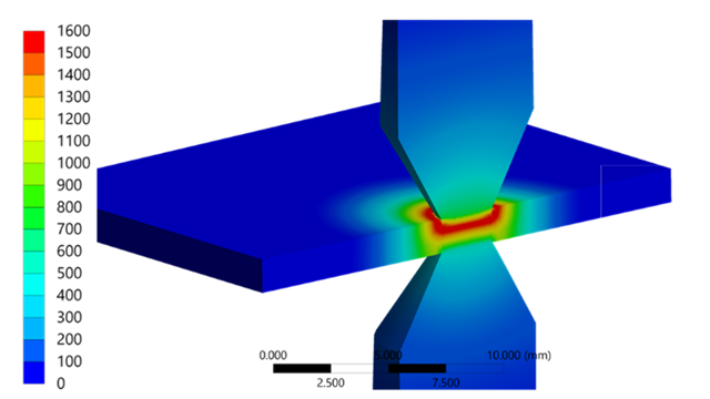
Mesh testing in structural analysis | © CADFEM Germany GmbH

Global basic settings

Over the last few versions, Ansys has developed a powerful tetrahedral mesh, which can be used to mesh the most complex components with just a few basic settings. To get an initial overview of the meshing behavior, I start with global settings. To do this, I determine 2 parameters from the geometry:

  1. Characteristic CAD size:
    Smallest dimensions to be resolved in the model (e.g. thickness of ribs). An element size can be estimated on the assumption that with square elements 1 element across the thickness is sufficient to correctly solve bending deformation, as well as the knowledge that up to an aspect ratio of 1:3 the error remains small

  2. CAD Cutoff:
    This is the size above which CAD details should no longer be resolved because they do not contribute to stiffness. Mesh defeaturing can be derived from this size.

Blog_TechArtikel_Vernetzung_Netzerstellung

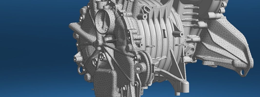
Mesh creation of a motor block housing with basic settings | © CADFEM Germany GmbH  

Only the settings shown above were made for the geometry shown: Element Size, Adaptive Sizing and Defeaturing. With ~500,000 nodes, this initial mesh provides a solid basis for modal analysis, deformation analysis and temperature field analysis. It has the advantage that, despite the complex structure, we only obtain a few elements, but the stiffness is resolved within the desired framework. The mesh is very uniform and structured and provides acceptable element qualities and aspect ratios. A modal analysis with double mesh refinement shows that the global stiffness is already perfectly resolved here. By the way, you can learn this and other practical tips in our meshing training: "Meshing in Ansys Mechanical".

Blog_TechArtikel_Vernetzung_Modenvergleich

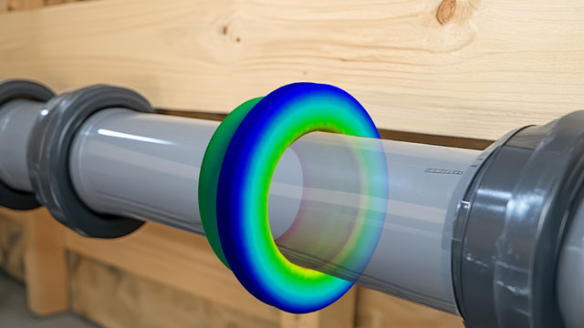
Mode comparison of two meshes | © CADFEM Germany GmbH  

The disadvantage of this mesh is that the structure is not completely resolved in very localized areas. As we have already established, this has no influence on the global stiffness and we can actually save ourselves from the tiresome discussion about this. Nevertheless, it should be noted that we obtain this "fast" mesh at the cost of slightly poorer element quality and locally poorer resolution. This can lead to the following problems:

  • Convergence problems due to local instabilities
  • Contact problems due to excessively coarse nets
  • Poor detection of stress peaks

Instead of the brute force method (halving the element edge length), the Curvature and Proximity functions are used in the next section.

mechanical_meshing_cadfem_seminar_13131


Tip

Practice-Oriented Meshing in Ansys Mechanical

Optimize your networking strategy! Attend our seminar and increase your efficiency in simulation!

Learn more

Extended functionality through Curvature and Proximity:

The attentive simulation engineer will have noticed that so far we have only used the first half of the automatic mesh settings in Ansys. With Curvature and Proximity, we now have functions at our disposal with which we can tackle precisely such weak points, as discussed in the last section. Curvature is a method with which we can influence curves and Proximity refers to gaps or thin ribs. In this way, details can be finely resolved and in all other areas the mesh stays coarse. This leads to fewer elements than the brute force method, but to a better resolution compared to the first basic settings. 

Blog_TechArtikel_Vernetzung_Detailbereich

Detail area with three different basic settings
(left: coarse basic mesh, center: fine basic mesh, right: coarse basic mesh and curvature)
| © CADFEM Germany GmbH

The advantages are that a few settings automatically generate a mesh that can resolve both the global stiffness and the details that are important for contact calculations and stress evaluations. Another advantage over pure element size halving is that elements are only refined where necessary and not everywhere. The clear disadvantage is an increased number of nodes and elements. This means that we save engineering time in CAD preparation and a few steps in the iterative meshing process and buy this with more simulation time. This is where you, as the engineer, have to decide which path you want to take.

Of course, the following settings will never be applicable to all geometries, but I will give them to you as a good starting point (following illustration). Element size and Defeaturing are determined as before. You can see that the element size can be set slightly larger (previously 8mm). This is because we previously had to find a balance between small features and large areas. Now, however, the mesh can be coarser on the large surfaces, as we will cover the details with Curvature. Activate Curvature (or / and Proximity) and select a value close to the Defeaturing tolerance for the min. sizes (the mesh must not become smaller). Also select a normal angle that controls the fineness of the radii. 120° has proven to be a good starting value.

Blog_TechArtikel_Vernetzung_Globale-Netzeinstellungen

Global mesh settings | © CADFEM Germany GmbH  

5.    The icing on the cake – scripting

We should actually have covered any geometry constellation with the mechanisms shown above, as well as a variation of those settings. We can decide between coarse meshes specifically for special applications or fine "all-rounders". Nevertheless, one or the other will find that geometries fall through the cracks or that meshing requirements are different. Automation is good when it cover a wide range of possibilities with just a few restrictions. Otherwise, we either have poor results or too few suitable applications. However, this also means that we can never use automatisms or basic settings to cover all cases in a meaningful way.

You can already guess what solution I can offer you here. That's right: scripting. A buzzword that is now echoing through every corridor. Ansys has been standardizing and simplifying scripting for several versions, so that it has now become an integral part of many simulation tasks. Watch out! When I used to think of scripting, I immediately thought of full automation. However, a much, much more powerful part is "scripting on the fly" using small code snippets. I can enter these snippets into the console while building the model to effectively complete small tasks that would otherwise require a lot of clicks and nerves.

Blog_TechArtikel_Vernetzung_Beispielskript

Example script for the meshing of bolts | © CADFEM Germany GmbH  

The script handles bolt meshing, for example, in a very elegant way. Select all bolt bodies, here via a string, and assign the Sweep/Axisymmetric meshing method, which results in a nice hexahedron mesh for this type of body. A local meshing size is then applied to the bolts so that bolt pretension and contacts in the support area are well mapped and no convergence difficulties arise.

Blog_TechArtikel_Vernetzung_Schrauben-Bohrungen

Meshing of bolts and boreholes | © CADFEM Germany GmbH  

Summary and recommendation

Meshing is often a process regulated by customer specifications or guidelines that have been developed over time. However, you should occasionally put your approach to the test and see whether it is better to throw old / outdated procedures overboard. Modern and powerful meshing algorithms, such as those implemented in Ansys, automatically generate meshes in the most complex structures. In order to be able to mesh as many structures as possible with these automatisms, only a few basic settings (adaptive sizing, defeaturing) are required, which you derive from your model. Special additional functions (Curvature and Proximity) allow you to resolve local areas in detail in addition to the global stiffness.

There’s more than one way to skin a cat and everyone meshes a little differently. The overall concept must be right! You can mesh with linear elements, only much finer, so that you get sufficient result quality. You can get so coarse that only the global stiffness is right, but you also have to accept that not every local detail is perfectly resolved. You can use different mesh densities to gain insights into model structure, stress evaluation and convergence behavior. Or you can use the longer calculating all-rounder mesh for as many tasks as possible. There are a variety of strategies and they all have their advantages and disadvantages. In the “Practice-Oriented Meshing in Ansys Mechanical” training course, you will learn suitable meshing procedures depending on the application and, if necessary, you can integrate these findings automatically using scripting. For this, I would like to recommend the “Automation within Ansys Mechanical using Python” training course.

As a final word, the following note: Of course you will find places in the meshes shown here that are not perfect and of course I can still rework them manually. But that was not my intention. I wanted to show that I/you/any user can automatically generate very good meshes in Ansys with a few solid basic settings, especially for complex and thin-walled structures. As an engineer, I can save myself a few hundred clicks and hours of CAD/meshing work with a clear conscience, accept a few less good elements and areas, but still achieve results of the desired quality. The art in FEM is, as in any numerical method, to minimize the error with reasonable effort, but be aware that you will never get it to zero.

Training on the topic

Portrait_Blog_OS

Autor

Oliver Siegemund

CAE Engineer

+49 (0)8092 7005-723
osiegemund@cadfem.de

Portrait_JNE_Blog

Redakteur

Jörg Neumeyer

CAE Engineer

+49 (0)8092 7005-766
jneumeyer@cadfem.de

Technische Redaktion

Dr.-Ing. Marold Moosrainer

Head of Professional Development

+49 (0)8092 7005-45
mmoosrainer@cadfem.de