Verifiably strong with FKM: Proof of strength made easy

Are your components really as reliable as you think? An incorrect strength assessment can be quite costly. With the FKM guideline and Ansys, you can ensure that your designs can withstand the real loads.

Blog_TechArtikel_FKM_Header
Strength assessment for an engine mount | © CADFEM Germany GmbH, Geometrie: Courtesy of Ansys, Inc.

Are your stress results really meaningful?

A reliable and efficient strength calculation for an engine mount is required. However, for this we not only need the results of a stress analysis, but first and foremost an accepted evaluation concept. Both the stress determination and the evaluation of the stresses with regard to component failure are derived from this. In mechanical engineering, the FKM guideline was established for this purpose. It allows the evaluation of local stresses, which means that we can directly input our FE results, for example, at a critical point of verification or an FE node. The guideline guides the user through the complete verification process and also provides the relevant influencing factors.

To illustrate a typical FKM verification, let’s consider the following example task. During the assembly of an aircraft turbine, it is temporarily mounted in a bracket so that components can be attached to the underside. We can assume a load of 10 tons, which will be distributed unevenly across the mounting points. When analyzing the stresses, we find that the bracket is subject to maximum stresses of between 110 and 270 MPa, depending on the load case. We choose a spheroidal graphite cast iron EN-GJS-800-2 as the material. The question now is whether the component can be approved in terms of its strength in relation to the stresses that occur.

Blog_TechArtikel_FKM_Randbedingungen

Boundary conditions for the simulation of an engine mount with Ansys Mechanical | © CADFEM Germany GmbH, Geometrie: Courtesy of Ansys, Inc.

Why is FKM verification essential for reliable constructions?

Reliable statements regarding strength are not possible based on stresses alone. Although all maximum stresses are below the tensile strength, it is not clear whether all factors relevant to strength have been taken into account, nor whether there is sufficient certainty against component failure. One common option would be to verify this through testing. However, as only a small number of parts are manufactured, experimental validation is problematic in this case for economic reasons and it is better to use an analytical strength assessment of components in accordance with the FKM as an established set of rules.

The FKM guideline covers steels, cast iron materials and aluminum alloys at normal operating temperatures. It guides the user through both static and fatigue assessment for the base material as well as for weld seams. This means that all typical tasks can be handled (internationally) in a consistent manner using this guideline. The guideline is constantly being updated; the 7th edition is dated 2020 and the 8th edition is expected in 2026. 

Blog_TechArtikel_FKM_Von-Mises-Spannungsverteilung

Von-Mises Stress distribution of an engine mount | © CADFEM Germany GmbH, Geometrie: Courtesy of Ansys, Inc.

Step by Step: How to make an FKM Assessment in practice

The FKM guideline does not provide any specifications for determining the stress and relies on a professional determination, usually by FEM. However, we now have to compare this with the material characteristics. The standard values for tensile strength, yield strength and elongation at break are typically available and must be adapted to the component. This includes design parameters such as component size and surface quality. The FKM guideline provides us with formulas based on empirical values from extensive tests. These factors are used to convert the material parameters to our component. We can then carry out a verification using these component parameters.

For the static analysis, we can also allow a certain degree of plastic strain, assuming sufficient ductility. There are a few points that need to be discussed in detail here, which you can find out more about in our first series of Let’s Simulate: Fatigue Strength, for example, where experts share their knowledge on the subject. Within the fatigue assessment, it should be noted that the mean stress and the amplitude do not necessarily have their maximum at the same point. Even with simple models, it can be difficult to select the critical position and the associated critical load case for a point-by-point calculation. Basically, we have to actually evaluate all points that could be critical.

The result is the so-called degree of utilization defined as the ratio of the existing stress to the permissible stress. This already includes the appropriate safety factors and must be less than 100% in order to provide a successful assessment. The guideline is based on standard values and a number of other conservative assumptions, so that the result as a whole can be regarded as conservative. If the verification according to the FKM guideline is successful, it can be assumed according to according to the recognized rules of technology, that no component failure is to be expected under the given loads.

Blog_TechArtikel_FKM_Ablauf-Nachweis

Basic procedure for fatigue strength verification in accordance with FKM, Rechnerischer Festigkeitsnachweis für Maschinenbauteile, 7. Auflage, VDMA Verlag, 2020 | © CADFEM Germany GmbH.

More than a standard: Why FKM inside Ansys makes the difference

The ‘manual’ procedure according to FKM is particularly time-consuming for fatigue verification. A large number of design parameters as well as the stress gradients normal to the surface have to be determined for each verification point, the latter being a rather unpopular undertaking for many FE calculators, as this variable is generally not available in a structural-mechanical post-processor. The exact position of the critical point cannot be determined in advance either, making it often necessary to analyze several points. In addition, there are special features, such as the equivalent mean stress, which must be determined in certain situations and taken into account in the assessment.

FKM inside Ansys solves these problems. This is a fully integrated extension for Ansys Workbench that enables automated strength verifications in accordance with the FKM guideline. The integration minimizes manual input, which increases both reliability and efficiency. We can simply select the entire surface for evaluation in the Ansys Mechanical model and do not have to limit ourselves to individual points. This saves us from having to discuss where the critical point might be.

The stress gradient is automatically determined and taken into account at each node. The software quickly processes the entire FKM formula. Special features such as surface hardening or special stress ratios are automatically taken into account. In the report, we not only receive the result, but also see all intermediate values.

Blog_TechArtikel_FKM_GUI

GUI of FKM inside Ansys for the static assessment | © CADFEM Germany GmbH  
TextImageTeaser_fkm


Tip

Strength verification for complex user-defined solid components

FKM verification for unwelded and welded components with FKM inside Ansys

Learn more

Blog_TechArtikel_FKM_Results

Extract from the automatic report of FKM inside Ansys | © CADFEM Germany GmbH  

FKM in action: degree of utilization for an engine mount

Let's return to our example. The engine mount is fixed at the bolting points and in each load case the intended 10 tons are distributed as a force of 100,000 N to the attachment points at the bottom. The dead load does not lead to any significant change in the result, which is why it was not considered further after an initial check. The loads occur between 0 and this maximum value. For the sake of simplicity, all load cases are calculated and the most critical is used for the verification.

The suspension is intended to support a 10-ton engine. We must therefore ensure that our verifications are reliable. Failure would be dangerous. In any FE calculation, it is important to use a sufficiently fine mesh to be able to make an accurate stress statement. I personally recommend working with a local mesh size and a growth rate of 1.1 - 1.3. To make this setting, you can deactivate adaptive meshing in the mesh control detail window. With the correct mesh size and growth rate, you can reliably determine the stress on the surface and the stress gradient in depth even with a coarser mesh. A mesh study is generally recommended for severe consequences of failure or a high degree of utilization.

Blog_TechArtikel_FKM_Spannungszustand

Stress state in the area of the refined mesh at the critical point | © CADFEM Germany GmbH  

Correctly interpreting stress results - here's how

At 480 MPa, the material's yield strength is significantly higher than the equivalent stress of 275 MPa. However, we have both severe consequences of failure and a casting that has not been tested non-destructively at every point with a low elongation at break. Both can be critical and are taken into account in the safety factor. The overall safety factor is then 2.3 according to FKM. If you now compare the yield strength with the existing stresses, the static assessment is the critical one based on the numbers. Due to the material and the stress ratios, we can statically allow a local plastic strain of 0.6% and use this to increase the permissible elastic calculated stress. This ultimately results in a utilization factor of 94%.

The CADFEM training provides comprehensive information on verification and numerous comparisons to everyday examples. Many thanks to the great lecturer for sharing the knowledge in such an exciting and exhilarating way.
Frederic-Hackl
Frederic Hackl
Bleckmann GmbH & Co. KG

The fatigue assessment shows a degree of utilization of 142%. Therefore, possibilities were sought to increase the permissible amplitude. A fatigue strength assessment is not necessary, as 200,000 cycles are sufficient. The surface factor is a parameters that has a significant influence and can also be changed by manufacturing measures. With the surface roughness that was achieved in the current state, for example, the surface factor reduces the allowed amplitude by 22%. If the critical areas are reworked so that an average roughness of 20 µm is achieved, this influence is reduced to 12%.

The combination of these two measures, allowing plastic strain for the static assessment and higher surface quality for the fatigue assessment, reduces the degree of utilization to below 100%. This means that the assessment was successful within the framework of the guideline.

Blog_TechArtikel_FKM_Auslastungsgrad

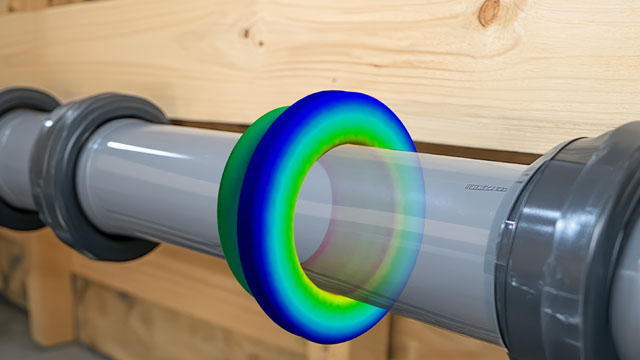
Degree of utilization for the fatigue assessment of the engine mount | © CADFEM Germany GmbH, Geometrie: Courtesy of ANSYS, Inc.  

Your next step: How to optimize the application of the FKM guideline

In this article, the general workflow of an FKM assessment was outlined using an example. Aspects such as different proportional or non-proportional loads or load spectra have not yet been considered. In our three-day CADFEM FKM Training, we will go into detail on the comprehensive contents of the FKM guideline and its application with Ansys Mechanical using practical exercises. You are also welcome to give feedback on which aspect of the guideline you are particularly interested in so that we can incorporate this into our Trainings & e-Learnings and Let’s Simulate Series.

Training on the topic

Portrait_FMA_Blog

Author

Florian Mailänder

CAE Engineer

+49 (0)8092 7005-900
fmailaender@cadfem.de

Portrait_JNE_Blog

Editorial

Jörg Neumeyer

CAE Engineer

+49 (0)8092 7005-766
jneumeyer@cadfem.de

Technical Editorial

Dr.-Ing. Marold Moosrainer

Head of Professional Development

+49 (0)8092 7005-45
mmoosrainer@cadfem.de