Distorted Metal 3D-Prints? Try ANSYS Process Simulation
Manfred Maurer
17.07.2024
Tech Article | 24/07
Additive manufacturing (AM) has surpassed the peak of its hype curve and new challenges await on the way to industrialization. While design freedom is alluring, the complexity of the process cannot be underestimated. Simulation tools can help the AM engineer get successful prints – the first time. In this article, we show how to combat part distortion, reducing it by 6x.

Additive Manufacturing – Hype or Hope?
Additive manufacturing (AM) – commonly known as 3D printing – has been hailed as the next revolution in manufacturing. From printing houses to your own car at home, everything seemed possible. The layer wise approach, specifically in powder bed fusion based technologies, does in fact allow for great freedom in design. Typical applications such as patient-specific implants or lightweight aerospace parts utilize this freedom, as well as other advantages such as part consolidation, function integration or simply being able to manufacture parts that are impossible to produce otherwise. However, as many new and exciting technologies before it, AM has fallen victim to its own hype.
The realization is slowly sinking in that the complexity of the physics involved in the printing process presents challenges that need to be solved before AM can be implemented on an industrial scale. But I’m convinced that we are past the peak of inflated expectations and the trough of disillusionment on the classic Gartner Hype Cycle, and we are now climbing the slope of enlightenment. The first step in solving a problem is realizing that it exists, and while the promise of AM is still very enticing, there is a lot of work ahead. I believe that simulation can help tackle these challenges and successfully bring AM to a wide variety of applications, with accuracy, scalability, and cost effectiveness.
In the next few sections, we will discuss a possibility of how to use the simulation of the manufacturing process itself to a-priori predict one of the main plagues of 3D printing: part distortions. The goal will be to get a print right the first time, without time and money consuming trial and error approaches.

Hype Curve for new technologies (left) | © CADFEM (Suisse) AG. Complexity for free: The promise of AM (right) | © Adobe Stock
3D Printing Challenges – Distorted Metal Parts
First, let’s get back to the challenges of AM, focusing on metal laser powder bed fusion (LPBF). This method takes a layer-wise approach, depositing fine metal powder into a build chamber one layer at a time, which is scanned by a laser, melted, and fused with already printed layers below. At its core, this is a multiscale problem: on the length scale, we deposit layers of 50µm, but a part can be hundreds of millimeters large; on the temperature scale, we melt powder at several hundreds of degrees, while the part must cool to room temperature before being processed further; finally on the time scale, powder is melted and solidifies in milliseconds, but printing an entire part can take hours or days.
While there are many more factors that influence the success and quality of a 3D print, such as powder quality, shielding gas flow, part position on the build plate, etc., the main challenges arise from the core physics: heating and melting powder, fusing it with surrounding solidified material and cooling it down, all in a cyclic manner layer by layer. Thermo-mechanically speaking, the rapid heating and cooling process leads to a build-up of thermal strains, which in turn results in residual stresses within the part. These are not directly visible of course; however their consequences are: cracks forming, separation of the part from its support structure, and most of all, part distortion, which is the focus of this article.
If distortion becomes excessive, the part can become out of spec, or might need expensive and prolonged post processing steps to bring it back into spec. This can range from a simple grinding process to the brute force use of a crowbar to bend the part back into shape. Over the next sections, we will illustrate a workflow to predict part distortions in-silico and pre-compensate them. While distortions might be reduced using certain measures – intelligent part design, adapted machine parameters or post-print heat treatment – we cannot outsmart physics and eliminate them completely. Instead, we pre-deform the part such that the typical upward bending works in our favor and deforms the part to the nominal CAD geometry.
Rethink your AM Design Process
A successful AM part starts with proper design. A cast part, for example, is typically not well suited for 3D printing. As with other traditional manufacturing processes, AM has its own set of design guidelines, often summarized as Design for Additive Manufacturing (DfAM). One desirable design feature is the avoidance of support structures. Supports fulfill two main purposes: mechanically anchoring the part to the build plate and thermally managing heat flux, as they divert energy away from sensitive regions during the build, reducing failure rates. However, supports are cumbersome to remove, and while they are typically inevitable in complex designs, they can be minimized by designing a self-supporting part.
One other typical design goal for AM parts is weight reduction. Without the constraints of traditional manufacturing processes, significant material savings can be achieved, contributing both to weight and cost savings. The prime method for taking advantage of the design freedom in AM is topology optimization, which allows the computer to find optimal material distribution for peak mechanical performance without unnecessary weight. While these typically nature-inspired generative designs with organic shapes are impossible to manufacture with traditional methods, they go hand in hand with 3D printing. Let’s look at a practical example.
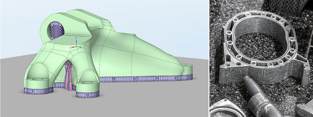
The bracket pictured below might be familiar to the avid reader, showing up in our deep dive into topology optimization. Here we want to go one step further and introduce an additional design constraint: the AM overhang constraint, which prevents the algorithm from depositing material with overhang angles below 45°, if possible. We generate a structure that is not only light-weight and mechanically optimal, but also self-supporting, minimizing the need for support structures and post processing effort. Those that are necessary – e.g. spanning the entire underside of the part to enable removal from the baseplate – can be generated externally, using various support types tailored to the needs of the design.

From original bracket before topology optimization to topology optimized bracket with AM overhang constraint to part with a variety of support types. | © CADFEM (Suisse) AG
Layered Approach for SLM Process Simulation
But design is not everything. As stated earlier, we cannot defeat physics. However, we can use its special characteristics to our advantage and compensate for distortions in advance so that the final printed part conforms to our tolerances. For that to work, we first must predict these distortions. This is where numerical simulation of the SLM process itself can be a very helpful tool in our box of tricks to avoid failed prints. To find the best compromise between speed and accuracy of simulation, we use the so-called lumped layer approach in a thermal-structural coupled analysis. Here we lump several real print layers into one simulation layer, as in-plane thermal and mechanical effects are more dominant than out-of-plane effects.

Workflow within ANSYS Workbench and AM Process Sequence determining simulation steps. | © CADFEM (Suisse) AG
Each simulation layer is then activated sequentially, and its thermal history is computed – from deposition, cooldown between layers, to final cooldown to room temperature. This thermal history field is then mapped onto a structural analysis, where its effects on the mechanics are evaluated layer by layer. Due to sequential cooldown and reheat by consecutive layers, thermal shrinkage strains accumulate in the part, leading to residual stresses after print. These are released during separation of the part from the baseplate, leading to distortions. This described birds-eye-view workflow is implemented within ANSYS Mechanical and guided by a setup wizard, where the process can be adjusted in detail.

Sample image of the LPBF Model Setup Wizard. | © CADFEM (Suisse) AG
An extensive material library with pre-implemented widely used AM materials is available and can be extended with your own materials. The finite element mesh is automatically generated in a layered fashion to facilitate the activation of sequential layers. In this example, a layered tetrahedron mesh is used for the part in order to optimally capture curved geometry features. The supports are voxelized and homogenized. Contact algorithms that thermally and mechanically link the supports to the part and baseplate are selected automatically. The setup is completed by defining machine parameters such as deposition thickness or scan speed, which have an influence on the thermomechanical behavior of the part during the process.

Detailed view of layered tetrahedron mesh for part and voxelized mesh for homogenized supports. | © CADFEM (Suisse) AG
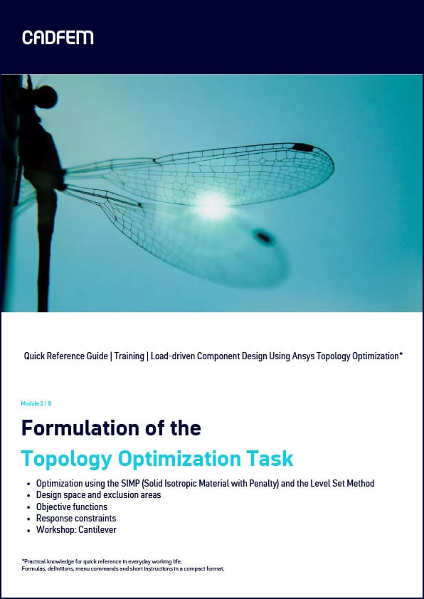
Quick Reference Guide (QRG): Formulation of the topology optimization task
The QRG provides you with an excerpt from our training course “Load-driven Component Design Using Ansys Topology Optimization”. Practical knowledge for quick reference in your day-to-day work, formulas, definitions, menu commands and short instructions in a compact format. Are you interested in the entire training course on this topic? You can find all the information here!
Download QRG for free
From Temperature Distribution to Recoater Interference
Once the simulation is complete, we can have a look at the results. The time history of the temperature field already allows for insight into the printing process and design of the part. Large temperature gradients in the vicinity of hot spots due to local accumulation of energy can lead to large local distortions or even cracking. This effect can be mitigated, for example, by changing the part design to have a more gradual cross-sectional transition or by adding support structures in the region to improve heat conduction away from the hot spot and down to the base plate. Cold spots can be an indication of lack of fusion of adjacent layers and can also be addressed by design or support changes.
However, mechanical results are the most significant in determining print success. Large local strains can be indicative of potential cracks. Large normal stresses in the interface between part and support can be a sign for support separation. Deformation in print direction during printing can be detrimental to powder distribution or even lead to the recoater blade crashing into the unfinished part, not only ruining the print but potentially damaging the machine. This special recoater interference result can be seen in figure 7, with red showing the most critical areas. These out of plane deformations could be reduced by adding small local support regions to better anchor the area to the baseplate.
Of course, the main result of interest is typically the residual distortion of the part after removal from the baseplate and supports. This classic “banana” effect stems from the release of residual stresses when the mechanical anchor to the base plate, i.e. the support structure, is cut off. Since the separation happens gradually from one direction, the stresses also tend to be released gradually, leading to asymmetry of the distortions. This effect can of course be simulated and taken into account when taking countermeasures against a distorted part. Figure 8 shows the asymmetrical bending in the bracket due to a gradual separation from the baseplate in positive x-direction.

Temperature distribution after cooldown of one layer; equivalent plastic strains after build; recoater interference as a measure of maximum distortion of each layer during print. | © CADFEM (Suisse) AG
Pre-compensating a Warped 3D Print
Now that we have virtually printed the part and predicted its distortions – which are typically out of spec – where do we go from here? How can we make sure that the final print comes out as intended and within spec? While there are design strategies and machine setups to reduce distortions, again, physics cannot be cheated. Heat treatment after printing can reduce residual stresses and resulting deformations, however it requires expensive hardware and machines to enable this time intensive post processing step. One might even think about a brute force approach – bending the part back into shape using crow bars and other crude tools, which is not efficient for large quantities and risks damaging the part.
The most efficient way to combat distortions is to accept them and use them to our advantage by pre-distorting the CAD in the opposite direction. The AM process will again inevitably lead to part distortion, which – if done correctly – counteracts the pre-applied deformation such that the final part is closest to the nominal CAD. While this pre-compensation can and has been done manually in the CAD, it can be time consuming and is not very accurate due to the nonlinearity of the process. Parts need to be printed, measured, compensated in the CAD, and printed again, in the worst case, several times. Simulation now opens the door to a much more automated and accurate pre-compensation workflow.
As we now know the 3D deformation field for the entire part as a result of the process simulation, we can simply apply this to the part volume, only in the opposite direction. Simply put, wherever the part bends upwards, we pre-bend it downwards and vice versa. Due to the nonlinear nature of the physics involved, it is not a simple single compensation with factor -1. Instead, the process is typically done iteratively with several sequential compensation steps. In practice, a factor of -0.75 has proven to be a good initial guess to bring the part close to nominal CAD after print. All this can be easily done in ANSYS SpaceClaim Direct Modeler, which allows a 3D displacement field to be mapped onto a CAD or STL file.

Out of plane distortion of the part after print and support removal; pre-compensated geometry (red) with factor -0.75; pre-compensated geometry after print and support removal (yellow). | © CADFEM (Suisse) AG
The Holy Grail of AM – Printing Correctly the First Time
Comparing the compensated part after print to the nominal CAD geometry, the deviation is significantly reduced, with a slight protrusion on the left, where separation from the baseplate and thus stress release begins. One could argue that this is already satisfactory. However, due to the largely automated workflow, additional compensation is easy to execute. Applying another compensation factor of -0.3 onto the already compensated part yields an almost perfect match between nominal CAD and part after printing. Deviations go from 2.83mm for the uncompensated part to 0.48mm in the second compensated part, a factor of almost 6. All while not wasting a single grain of metal powder or valuable machine time.

Left: Deviation plot of initially predicted distorted part compared to nominal CAD (red/blue: out/inside deviation >0.1mm). Maximum deviation 2.83mm outside, 2.45mm inside; Right: Deviation plot of final pre-compensated distorted part compared to nominal CAD (red/blue: out/inside deviation >0.1mm). Maximum deviation 0.44mm outside, 0.48mm inside. | © CADFEM (Suisse) AG
To summarize, simulation of the AM process can be a powerful tool to combat the main challenges that still hamper this production method from scaling up, namely part distortions and low geometric precision. From unlocking the full potential of design freedom through topology optimization, to using a simple, guided workflow to compensate and significantly reduce inevitable distortions – within the ANSYS Additive world, you are free to virtually experiment and improve your designs without costly prototypes or failed prints. It can also help you become a better AM engineer by not only helping solve immediate problems, but also gain valuable insight into the complex process itself.
While we have mainly focused on part-scale solutions, there is much more to discover on the micro- and meso-scale. You might be interested in optimal machine settings to save time and energy but still have acceptable melt pool dimensions, or the best hatch pattern to have a dense part without lack-of-fusion porosity, or the influence of your machine parameters and scan pattern on local microstructure of the crystal lattice forming due to the rapid heating and cooling process. All these types of simulations can be done with ANSYS Additive Science, a more in-depth tool focused on local micro-scale phenomena.

Simulations at micro-scale: meltpool dimensions and crystal microstructure. | © CADFEM (Suisse) AG
Training on the topic
-
Simulating Additive Manufacturing Processes in Metal Printing

In this training, you will learn to use Ansys Mechanical to simulate the 3D printing process for components in order to optimize geometry, component orientation & warpage.
-
Load-driven Component Design Using Ansys Topology Optimization

Automatic generation and validation of an optimal material distribution in each design space under structural mechanical conditions.
-
Optimizing Additive Process Parameters for Metallic Materials

Determine optimal print parameters for the laser powder bed fusion process and influence printed component properties.
-
Intensive Workshop: Structural Mechanics

A must-have for all structural mechanics: After this workshop, you will look at your models with different eyes - guaranteed.


Editor
Dr.-Ing. Marold Moosrainer
Head of Professional Development
+49 (0)8092 7005-45
mmoosrainer@cadfem.de
Cover images: Left: © CADFEM GmbH | Right: © Adobe Stock
First published: April, 2024


