FEM in Mechanical Engineering: Integrated Ansys Workflow for the Assessment of Welds
Klaus Kuboth
20.04.2026
Efficiently Achieving FKM Compliant Strength Assessments – from the Complex CAD Model to a Reliable Evaluation in Ansys Mechanical.
A welded base frame for a truck trailer is a classic example of mechanical engineering: profiles, plates, cross members, mounting points for attachments, numerous weld seams, and bolted joints. From a design perspective, it appears familiar and seemingly manageable. At the same time, much depends on the frame’s ability to carry loads reliably in real-world operation, under varying loads, and over many years of service. We show you how to perform the required strength assessments in a way that is FKM compliant and practical for everyday engineering using Ansys Mechanical.
Summary
-
A truck trailer base frame may seem simple from a design standpoint, yet it places high demands on FEM modeling: imperfect CAD geometry, cyclic loading, and critical weld seams require precise model setup and evaluation.
-
Ansys Mechanical enables robust geometry preparation, locally refined meshing, realistic load cases, and submodels for critical weld regions – the foundation for stress evaluations in line with the FKM guideline.
-
With FKM inside Ansys and Weld inside Ansys, the manual Excel workflow becomes unnecessary. Evaluations, gradients, influence factors, and utilization ratios are generated fully integrated and consistent – ideal for variants and series products.
In practice, structures such as a truck trailer base frame are often assessed initially using simple approximations or CADintegrated FEM tools. For a rough evaluation of stiffness, this can work. However, as soon as loads increase, lightweight potential needs to be leveraged, or a standardcompliant, verifiable strength assessment is required, this approach reaches its limits. A stress plot alone is no longer sufficient at that point. This is precisely where Ansys Mechanical can make the difference.
Truck Base Frames: Apparently Simple, Yet Technically Demanding
A base frame for a truck trailer is designed to provide the required stiffness for a wide range of vehicle superstructures. For economic reasons, it is welded from standard profiles and plates. In the CAD environment, this results in a frame consisting of longitudinal and cross members, reinforced areas, support points, and numerous weld seams.
At first glance, this seems straightforward. In practice, however, it presents several characteristic challenges:
-
The CAD geometry typically originates from an early design stage. Plates overlap, there are gaps, offsets, and small irregularities. At this point in the design process, these issues do not matter because, during manufacturing, plates are adjusted on site and gaps are bridged. The model usually contains the weld preparations but not the welds themselves. As a result, the requirements for the CAD model differ between production and FEM analysis, which leads to meshing and evaluation issues.
-
The frame is not only subjected to static loads. During operation, it experiences alternating loads from braking, potholes, cornering, and uneven loading. These cyclic loads are especially critical for weld seams. While static conditions mainly endanger the structure around the weld, cyclic loading makes the weld itself the vulnerable point. Anyone relying solely on a single linear stress analysis risks overlooking important hazards or must compensate with large safety margins.

Structural model of a welded support frame used for detailed FEM analysis in Ansys Mechanical. | © CADFEM Germany GmbH
Deepen Your Knowledge: Whitepaper “Your Introduction to Professional FEM”
In this whitepaper, you will learn how to establish structural simulation in your company in a structured way, avoid common pitfalls, and understand the real importance of result quality, stability, and IT integration in everyday engineering practice. Two case studies illustrate how Ansys Mechanical is applied in real projects.
Download the whitepaper now and take a solid first step into FEM
Stress Evaluation According to the FKM Guideline
Anyone in mechanical engineering who wants to derive reliable statements about strength typically relies on the FKM Guideline “Analytical Strength Assessment for Mechanical Components.” The guideline defines:
- how material properties are transferred to the real component,
- how static and cyclic assessments are performed,
- how safety factors and influence factors must be incorporated, and
- how a utilization ratio is ultimately determined that clearly indicates whether the verification has been passed.
It is important to note that the FKM Guideline does not specify how stresses must be calculated. That task is usually handled by FEM. Instead, it defines how these stress results must be interpreted and evaluated.
For our truck base frame, this means that the local stress distribution at critical locations, such as along weld seams or at notches, is compared with the allowable stresses according to FKM. The outcome is a utilization ratio that quantitatively describes the available safety.

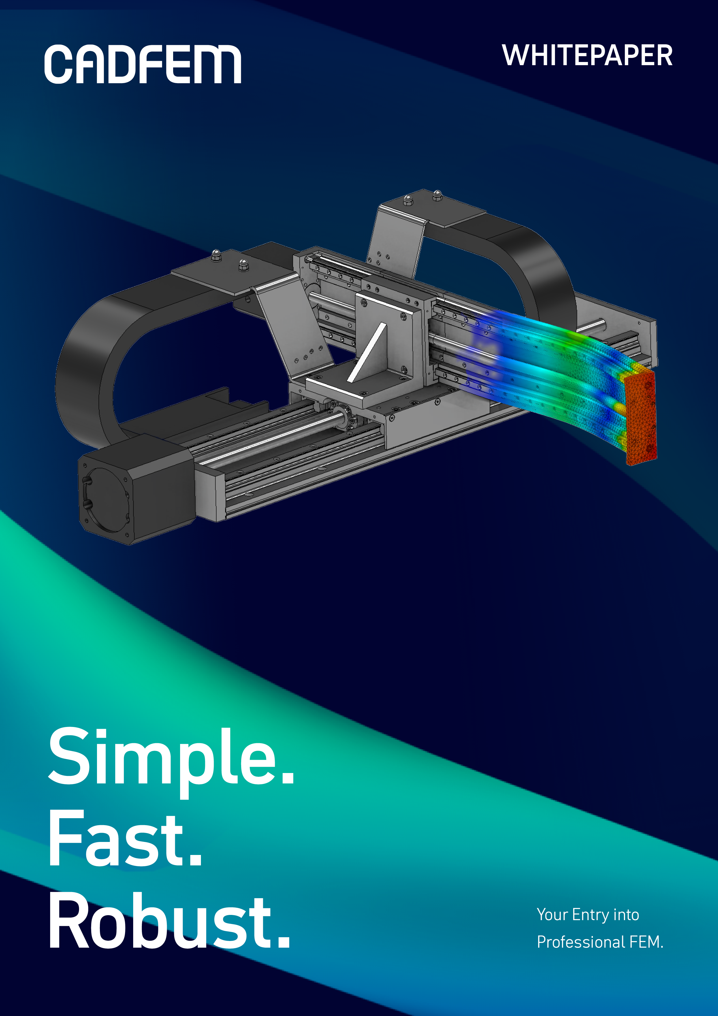
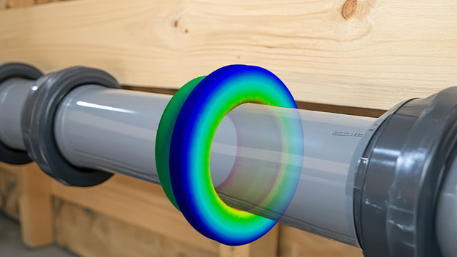
Automated fatigue strength report summarizing local stress spectra and utilization at critical weld locations. | © CADFEM Germany GmbH
From the CAD Model to the FEM Model with Ansys Mechanical
The first step is to transfer the design geometry into a simulation-ready FEM model. In Ansys Mechanical, this begins with the robust import of the base frame’s CAD data, for example in STEP, Parasolid, or native formats.
The model can then be prepared for simulation. Pure visualization details or assembly features that have no significant influence on stiffness can be removed. At the same time, problematic areas such as gaps, overlaps, or duplicate edges must be cleaned up. The goal is a geometric model that captures the relevant loadbearing mechanisms without being overloaded with unnecessary details.
The next step is modeling the weld seams. Which welds should be represented geometrically? Where should simplified substitute models be used? How closely should the FEM model reflect the real weld situation? These decisions depend directly on the level of precision required later, particularly for cyclic assessments.
The objective is not necessarily to represent the geometry as precisely as possible. A scanned geometry does not produce more accurate results in terms of verification. Instead, we must align the model with the requirements of the verification concept for which the allowable stresses are defined. These allowable stresses were determined using idealized representations, and the model must therefore follow the same logic.
Meshing comes next. Ansys Mechanical makes it possible to create a globally coarse yet highquality mesh while refining the critical areas locally. This ensures that both global stiffness and the local stresses in the region of the weld seams are captured with sufficient accuracy. For very large models, shell elements are often the preferred choice, supplemented locally with solid elements or submodels where needed.
Identifying, Refining, and Evaluating Critical Welds
A first simulation run provides the stress and deformation fields for all load cases under consideration. These results make it possible to identify the areas where the loading is particularly critical for the strength assessment. In cyclically loaded steel structures, weld seams are often the decisive verification point.
The identified regions are then prepared in a targeted way. This may involve refining the mesh, creating a submodel for a single weld seam or connection area, or aligning the weld modeling approach more closely with the actual manufacturing method. The goal is to achieve a level of stress resolution that is sufficiently detailed for an FKM compliant evaluation.

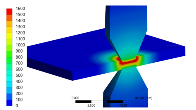
Static structural analysis showing von Mises stress contours under load. | © CADFEM Germany GmbH
Integrated Workflow Instead of an Excel Chain
In many companies, stresses are still calculated in one tool, manually read at selected points, and then transferred into an Excelbased FKM formula environment. This may work for individual assessments, but the manual steps make the process errorprone and only partially scalable, especially for larger frame structures with many potentially critical locations.
With FKM inside Ansys, the base material can be evaluated directly according to the FKM Guideline: material properties are adapted at the component level, influences such as component size, surface quality, and stress gradients are included, and a utilization ratio is determined at the end. Weld inside Ansys provides an additional, systematic weld seam evaluation based on suitable methods.
The workflow with Ansys Mechanical and FKM inside Ansys runs entirely within a single environment:
- Model setup, meshing, and solution in Ansys Mechanical
- Automatic extraction of relevant stress and gradient information
- FKMcompliant evaluation in FKM inside Ansys
- Report generation with intermediate values and final results at the push of a button
For the truck base frame, this means that repeated variants, such as modified plate thicknesses, reinforced beams, or additional attachment points, can be evaluated much more efficiently and consistently. The model does not need to be reworked from scratch each time, and the assessment does not need to be rebuilt manually for every iteration.
Fast Strength Assessments – FKM‑Compliant and Practical
The strength assessment of a truck trailer base frame is a typical case in which professional structural simulation can fully demonstrate its value. Robust geometry preparation and meshing, realistically defined load cases, targeted examination of critical weld seams, and FKM‑compliant evaluation are combined in a single integrated environment. The result is a set of findings that are not just “reasonably plausible” but fully aligned with the guideline and therefore reliable.
With Ansys Mechanical, design engineers gain a practical tool for professional structural simulation that goes far beyond a one‑time approximation. They do not need to be simulation experts to compare variants confidently or to identify reserves and weak points clearly. The outcome is a frame structure that is both safe and economically efficient.
Test Ansys Mechanical Now
If you are currently using CADintegrated FEM tools and are reaching their limits when performing strength assessments on frame structures, this is the ideal starting point: test Ansys Mechanical and FKM inside Ansys in a pilot project.
Working with a familiar component, you will quickly see:
- how cleanly your frame can be meshed and evaluated,
- how calculation stability and result quality improve,
- how much manual effort in model setup, verification, and reporting is eliminated.
This makes the difference between a CADintegrated approximation and a professional FEM workflow directly measurable. Schedule an initial consultation without obligation.
Do not miss our webinar “Why switching from CAD-integrated to Ansys Mechanical pays off”. We will present Ansys Mechanical using typical application examples and answer your questions in a clear and practical way.